
5DS44 Series specifications
The Monte Carlo Fan Company has established itself as a leader in the ceiling fan industry, and their 5DS44 Series is no exception. This series exemplifies a blend of modern design, advanced technology, and superior performance, making it an excellent addition to various living spaces.One of the most notable features of the 5DS44 Series is its sleek and contemporary design. Available in various finishes such as matte black, polished nickel, and white, the fans seamlessly fit into a range of interior aesthetics. The minimalist style ensures that they complement both traditional and modern decor, adding a touch of sophistication to any room.
The 5DS44 Series is equipped with an efficient DC motor, which not only enhances energy efficiency but also reduces noise levels significantly. This technology allows the fan to operate quietly, making it suitable for bedrooms, living rooms, or any space where tranquility is essential. The DC motor also contributes to lower energy consumption, making it an environmentally friendly choice that can help reduce electric bills.
In terms of performance, the 5DS44 Series boasts impressive airflow capabilities. With its 44-inch blade span, the fan is designed to generate optimal airflow, ensuring comfortable conditions in medium to large-sized rooms. The fan's aerodynamic blades are engineered for maximum efficiency, providing a refreshing breeze even at low speed settings.
Another key characteristic of the 5DS44 Series is its versatility in operation. The fans typically come with multiple speed settings, allowing users to customize their comfort level according to individual preferences and seasonal needs. Additionally, many models in this series offer remote control functionality, providing convenient access to speed adjustments and light settings from anywhere in the room.
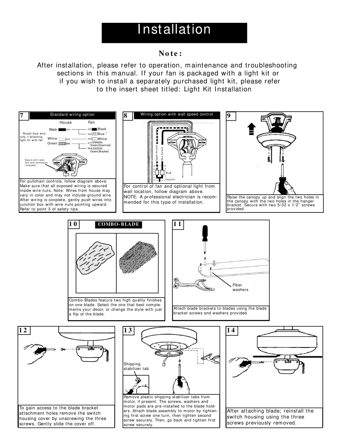
Installation is easy, as the Monte Carlo Fan Company designs its products with a user-friendly approach. The 5DS44 Series often includes a user-friendly mounting system that simplifies the installation process for both professionals and DIY enthusiasts.
In conclusion, the Monte Carlo Fan Company 5DS44 Series combines aesthetic appeal with cutting-edge technology and user-centric features. The combination of energy-efficient performance, striking design, and quiet operation makes this series an excellent choice for anyone looking to enhance the comfort and style of their home. Whether you are refreshing a modern space or adding a contemporary touch to a classic interior, the 5DS44 Series is sure to impress.