Installation
INSTALLING THE WRIST SUPPORT
The KBD5000 comes with three control modules that fit in three receptacles on the base. The setup from the factory has the jog/shuttle module installed on the left side of the base, the keypad module in the center, and the joystick module on the right.
The KBD5000 also has a wrist support that can be easily installed and removed (the keyboard can be used without the wrist support). This system allows custom tailoring of the keyboard to your preferences.
Perform the following steps to install the wrist support:
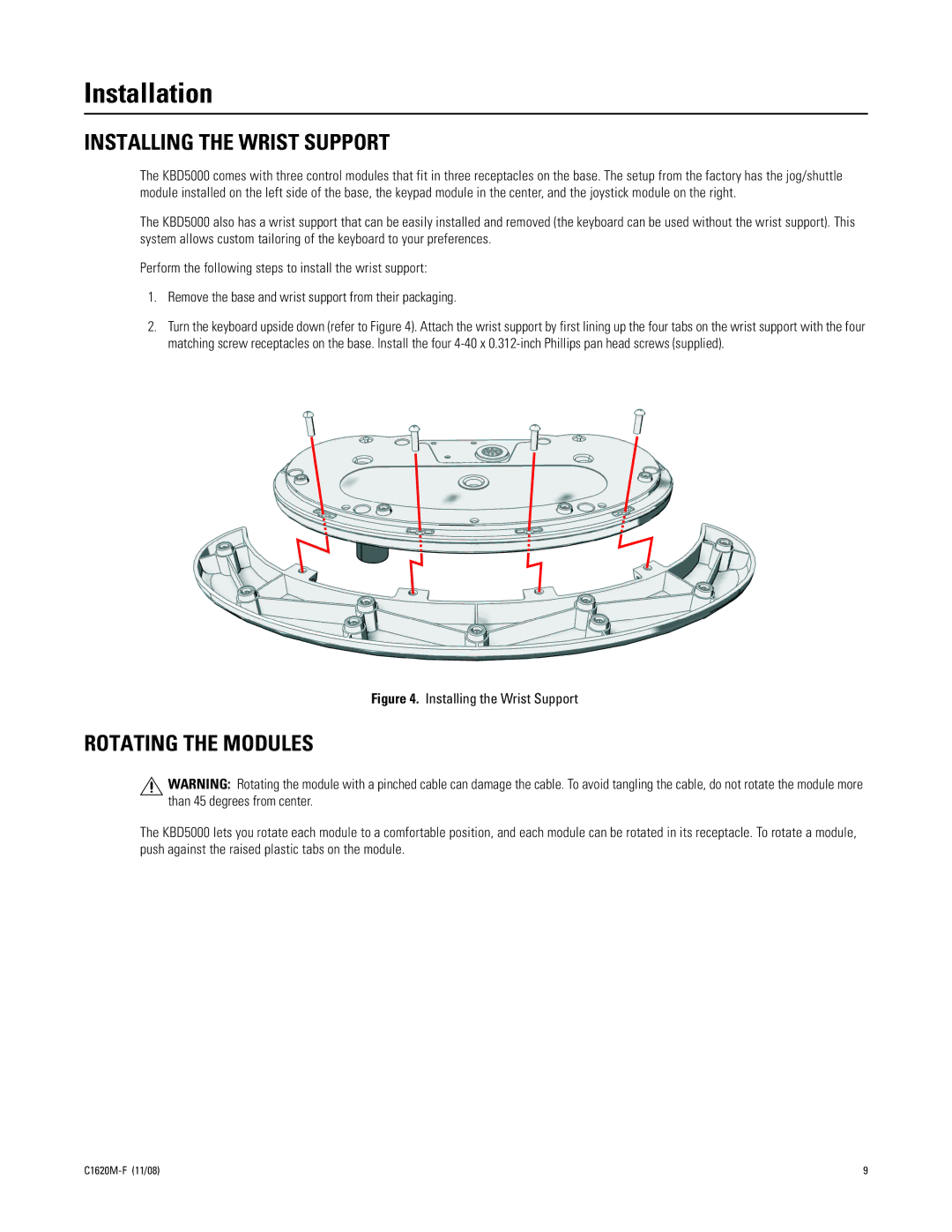
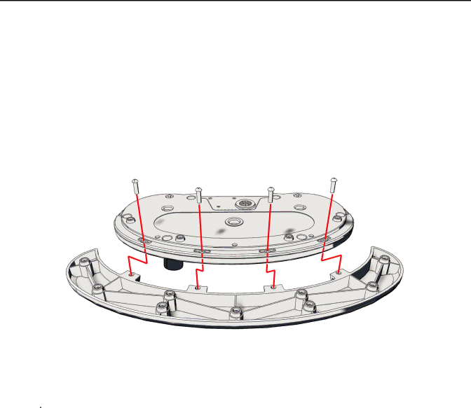
1.Remove the base and wrist support from their packaging.
2.Turn the keyboard upside down (refer to Figure 4). Attach the wrist support by first lining up the four tabs on the wrist support with the four matching screw receptacles on the base. Install the four
Figure 4. Installing the Wrist Support
ROTATING THE MODULES
![]() WARNING: Rotating the module with a pinched cable can damage the cable. To avoid tangling the cable, do not rotate the module more than 45 degrees from center.
WARNING: Rotating the module with a pinched cable can damage the cable. To avoid tangling the cable, do not rotate the module more than 45 degrees from center.
The KBD5000 lets you rotate each module to a comfortable position, and each module can be rotated in its receptacle. To rotate a module, push against the raised plastic tabs on the module.
9 |