
5MQ60XX specifications
The Monte Carlo Fan Company 5MQ60XX is an exemplary ceiling fan that blends innovative technology with stylish design, perfect for any modern living space. Renowned for its durability and performance, this fan is designed with features that prioritize user comfort and efficiency.One of the standout characteristics of the 5MQ60XX is its powerful motor, which ensures optimal airflow while operating quietly. The fan boasts a unique 60-inch blade span, making it ideal for larger rooms where effective circulation is crucial. The aerodynamic blades are crafted from high-quality materials, offering both stability and durability while also enhancing the overall aesthetics of the fan.
The 5MQ60XX comes with multiple speed settings, allowing users to customize airflow according to their preferences and needs. With a user-friendly remote control, adjusting the fan's settings becomes effortless, giving you the convenience to change speeds without leaving your seat.
In terms of technology, the Monte Carlo Fan Company incorporates energy-efficient LED lights in the 5MQ60XX model, providing not only effective illumination but also contributing to energy savings. This feature not only increases the overall functionality of the fan but also aligns with eco-friendly practices that a growing number of consumers appreciate.
The fan's sleek, contemporary design is another notable aspect. Available in various finishes, including brushed nickel and matte black, the 5MQ60XX can complement diverse decor styles, from modern to traditional. Its streamlined silhouette and elegant design make it more than just a source of airflow; it serves as a statement piece in any room.
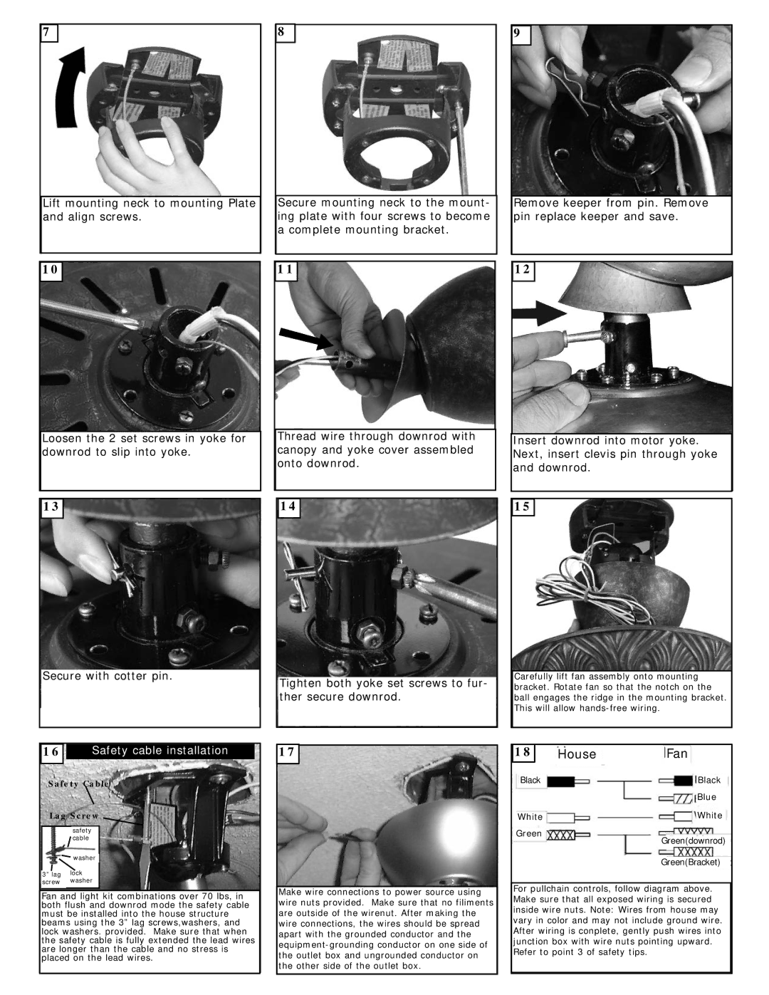
Installation of the Monte Carlo Fan 5MQ60XX is straightforward, thanks to its intuitive mounting system. Whether you choose to install it on a flat ceiling or a sloped surface, the fan adapts with ease, ensuring both reliability and performance.
In summary, the Monte Carlo Fan Company 5MQ60XX exemplifies the perfect blend of efficiency, technology, and style. With features like a powerful motor, customizable speed settings, integrated LED lighting, and attractive design options, this fan is an ideal choice for anyone looking to enhance their indoor environment with comfort and sophistication.