
DCT5100 specifications
The Motorola DCT5100 is a digital cable set-top box that became popular due to its innovative features and user-friendly functionalities. Designed primarily for the North American market, it is a pivotal component for cable television providers looking to deliver high-quality digital content to their subscribers.One of the standout characteristics of the DCT5100 is its ability to decode and display digital television signals. This allows users to access a broad array of channels, including high-definition (HD) programming, which enhances the overall viewing experience by providing superior picture quality and sound clarity.
The DCT5100 is equipped with a powerful processor that ensures quick channel changes and seamless navigation across menus. The intuitive interface makes it easy for users to browse through the electronic program guide (EPG), schedule recordings, and manage settings, making it accessible even for those who may not be technologically savvy.
Additionally, the device supports various technologies such as MPEG-2 and MPEG-4 video compression standards, allowing for efficient transmission of high-quality video over cable networks. This versatility means that the DCT5100 can adapt to different broadcasting environments and provides flexibility to service providers.
One of the key features of the DCT5100 is its interactive programming capabilities. It supports features like Video on Demand (VOD) and Pay-Per-View, allowing users to access a range of movies and shows at their convenience. This interactivity extends to features such as parental controls, enabling users to restrict access to certain channels or content, thereby ensuring a family-friendly environment.
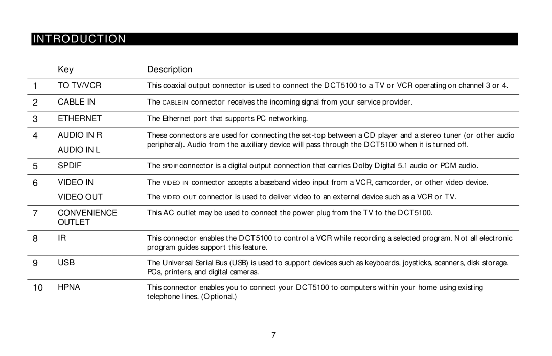
In terms of connectivity, the DCT5100 comes equipped with multiple output options, including composite, S-video, and HD component connections, allowing for easy integration into home entertainment systems. Additionally, it supports analog audio outputs, enhancing compatibility with a wide variety of audio systems.
Overall, the Motorola DCT5100 stands out as a reliable and feature-rich set-top box that has left a significant mark in the digital cable industry. Its rich suite of features, robust technologies, and user-centric design make it a strong choice for consumers seeking enhanced digital television experiences. Whether accessing the latest programming, enjoying high-definition content, or navigating effortlessly through channels, the DCT5100 remains a reliable option for cable viewers.