3
Pin Assignment
UPort DB9 Pin Assignments
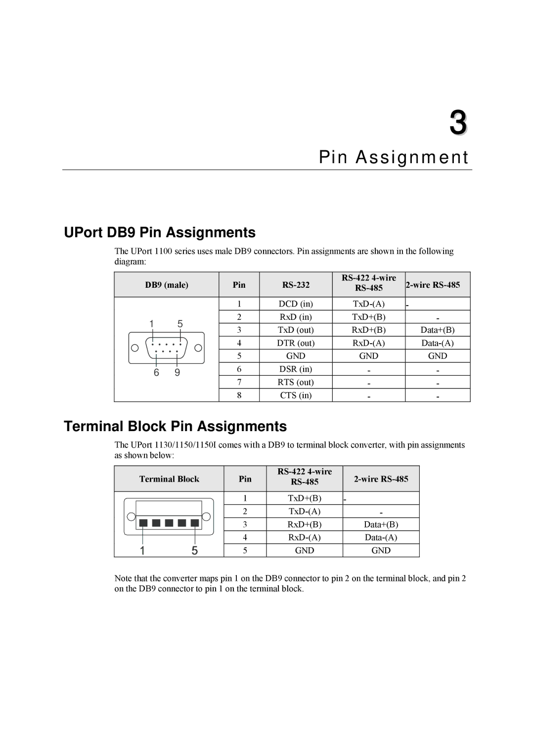
The UPort 1100 series uses male DB9 connectors. Pin assignments are shown in the following diagram:
DB9 (male) | Pin | |||||||||
|
|
|
|
|
|
|
|
| ||
|
|
|
|
|
| 1 | DCD (in) | - | ||
1 |
| 5 | 2 | RxD (in) | TxD+(B) | - | ||||
| 3 | TxD (out) | RxD+(B) | Data+(B) | ||||||
|
|
|
|
|
| |||||
|
|
|
|
|
| 4 | DTR (out) | |||
|
|
|
|
|
| |||||
|
|
|
|
|
| 5 | GND | GND | GND | |
|
|
|
|
|
| |||||
|
|
|
|
| 6 | DSR (in) | - | - | ||
6 | 9 |
| ||||||||
7 | RTS (out) | - | - | |||||||
|
|
|
|
|
| |||||
|
|
|
|
|
| 8 | CTS (in) | - | - | |
Terminal Block Pin Assignments
The UPort 1130/1150/1150I comes with a DB9 to terminal block converter, with pin assignments as shown below:
Terminal Block | Pin | ||
| 1 | TxD+(B) | - |
| 2 | - | |
| 3 | RxD+(B) | Data+(B) |
| 4 | ||
| 5 | GND | GND |
Note that the converter maps pin 1 on the DB9 connector to pin 2 on the terminal block, and pin 2 on the DB9 connector to pin 1 on the terminal block.
