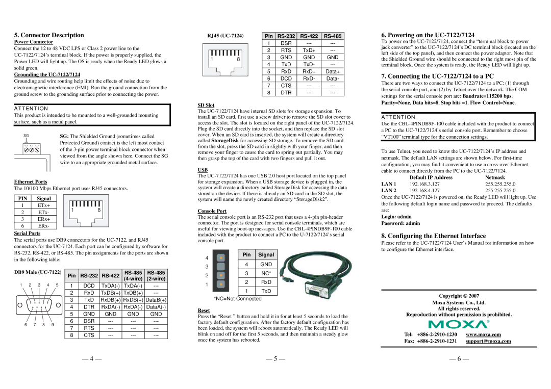
5. Connector Description
Power Connector
Connect the 12 to 48 VDC LPS or Class 2 power line to the
Grounding the UC-7122/7124
Grounding and wire routing help limit the effects of noise due to electromagnetic interference (EMI). Run the ground connection from the ground screw to the grounding surface prior to connecting the power.
RJ45
1 8
Pin | |||
1 | DSR | ||
2 | RTS | TxD+ | |
3 | GND | GND | GND |
4 | TxD | TxD- | |
5 | RxD | RxD+ | Data+ |
6 | DCD | RxD- | Data- |
7 | CTS | ||
8 | DTR |
6. Powering on the UC-7122/7124
To power on the
7. Connecting the UC-7122/7124 to a PC
There are two ways to connect the
settings for the serial console port are: Baudrate=115200 bps, Parity=None, Data bits=8, Stop bits =1, Flow Control=None.
ATTENTION
This product is intended to be mounted to a
SG | SG: The Shielded Ground (sometimes called | |||
|
|
|
| Protected Ground) contact is the left most contact |
|
|
|
| |
|
|
|
| of the |
|
|
|
| viewed from the angle shown here. Connect the SG |
|
|
|
| wire to an appropriate grounded metal surface. |
Ethernet Ports
The 10/100 Mbps Ethernet port uses RJ45 connectors.
SD Slot
The
USB
The
ATTENTION
Use the
To use Telnet, you need to know the
LAN 1 | Default IP Address | Netmask |
192.168.3.127 | 255.255.255.0 | |
LAN 2 | 192.168.4.127 | 255.255.255.0 |
PIN | Signal |
1 | ETx+ |
2 | ETx- |
3 | ERx+ |
6 | ERx- |
1 8
system will name the newly created directory “StorageDisk2”.
Console Port
The serial console port is an
Once the
Login: admin
Password: admin
Serial Ports
The serial ports use DB9 connectors for the
DB9 Male | Pin | ||||||||
1 | 2 3 | 4 | 5 |
|
|
|
| ||
1 | DCD | ||||||||
|
|
|
| 2 | RxD | TxDB(+) | TxDB(+) | ||
|
|
|
| 3 | TxD | RxDB(+) | RxDB(+) | DataB(+) | |
|
|
|
|
|
|
|
|
| |
|
|
|
| 4 | DTR | ||||
|
|
|
| 5 | GND | GND | GND | GND | |
6 | 7 | 8 | 9 | 6 | DSR | ||||
7 | RTS | ||||||||
|
|
|
| ||||||
|
|
|
| 8 | CTS | ||||
included with the product to connect a PC to the
4 |
|
| Pin | Signal |
|
|
|
| |
3 |
|
| 4 | GND |
2 |
|
| 3 | NC* |
|
|
|
| |
1 |
|
| 2 | RxD |
|
|
|
| |
|
|
| 1 | TxD |
| *NC=Not | |||
|
|
| ||
| Connected |
| ||
Reset
Press the “Reset ” button and hold it in for at least 5 seconds to load the factory default configuration. After the factory default configuration has been loaded, the system will reboot automatically. The Ready LED will blink on and off for the first 5 seconds, and then maintain a steady glow once the system has rebooted.
8. Configuring the Ethernet Interface
Please refer to the
Copyright ♥ 2007
Moxa Systems Co., Ltd.
All rights reserved.
Reproduction without permission is prohibited.
Tel:
Fax:
— 4 — | — 5 — | — 6 — |
