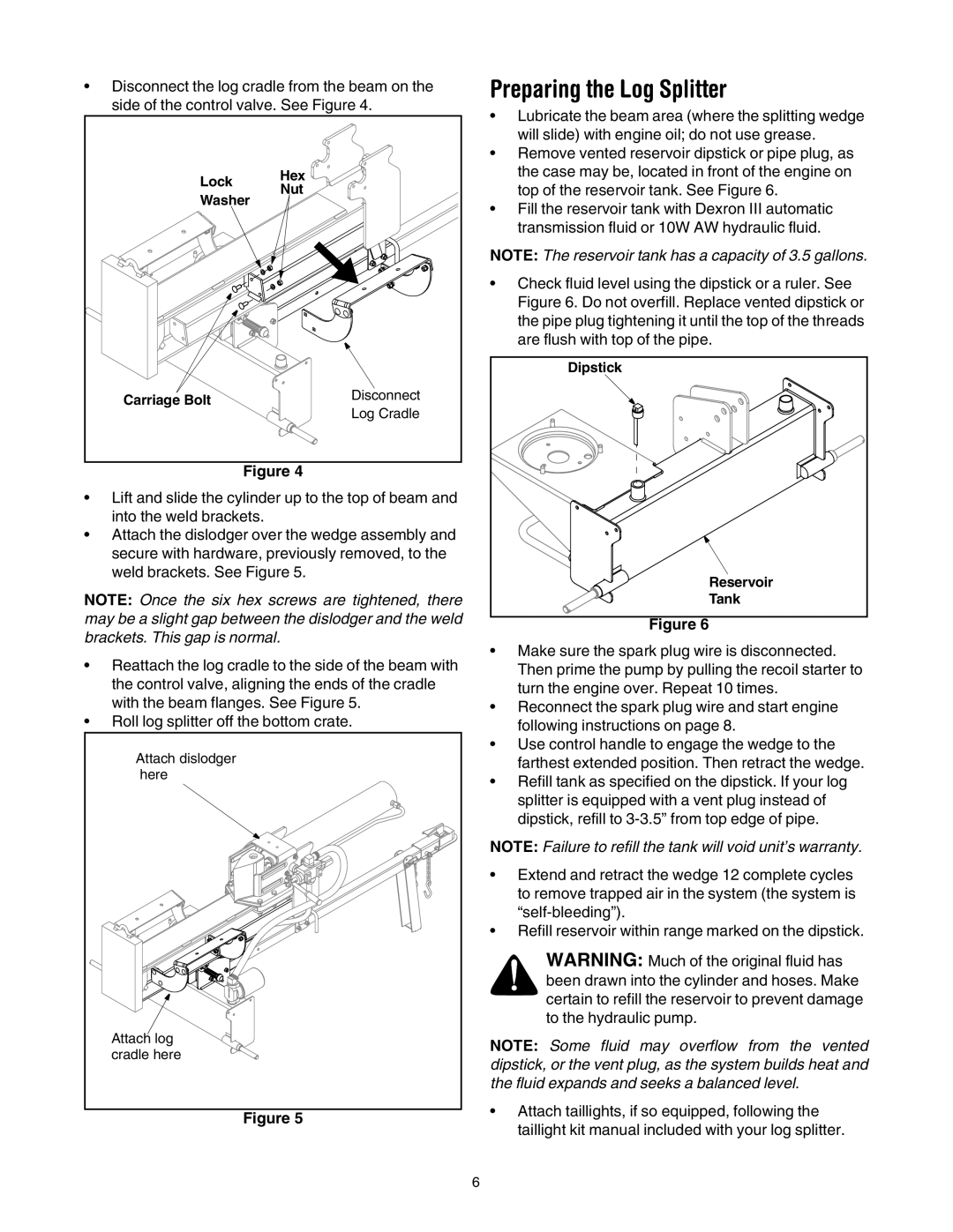
Disconnect the log cradle from the beam on the side of the control valve. See Figure 4.

Lock

Hex

Nut

Washer


Carriage Bolt

Disconnect

Log Cradle


Figure 4

Lift and slide the cylinder up to the top of beam and into the weld brackets.

Attach the dislodger over the wedge assembly and secure with hardware, previously removed, to the weld brackets. See Figure 5.

NOTE: Once the six hex screws are tightened, there may be a slight gap between the dislodger and the weld brackets. This gap is normal.

Reattach the log cradle to the side of the beam with the control valve, aligning the ends of the cradle with the beam flanges. See Figure 5.

Roll log splitter off the bottom crate.

Attach dislodger

here

Attach log

cradle here

Figure 5

Preparing the Log Splitter

Lubricate the beam area (where the splitting wedge will slide) with engine oil; do not use grease.

Remove vented reservoir dipstick or pipe plug, as the case may be, located in front of the engine on top of the reservoir tank. See Figure 6.

Fill the reservoir tank with Dexron III automatic transmission fluid or 10W AW hydraulic fluid.

NOTE: The reservoir tank has a capacity of 3.5 gallons.

Check fluid level using the dipstick or a ruler. See Figure 6. Do not overfill. Replace vented dipstick or the pipe plug tightening it until the top of the threads are flush with top of the pipe.

Dipstick

Reservoir

Tank

Figure 6

Make sure the spark plug wire is disconnected. Then prime the pump by pulling the recoil starter to turn the engine over. Repeat 10 times.

Reconnect the spark plug wire and start engine following instructions on page 8.

Use control handle to engage the wedge to the farthest extended position. Then retract the wedge.

Refill tank as specified on the dipstick. If your log splitter is equipped with a vent plug instead of dipstick, refill to 3-3.5” from top edge of pipe.

NOTE: Failure to refill the tank will void unit’s warranty.

Extend and retract the wedge 12 complete cycles to remove trapped air in the system (the system is “self-bleeding”).

Refill reservoir within range marked on the dipstick.

WARNING: Much of the original fluid has been drawn into the cylinder and hoses. Make certain to refill the reservoir to prevent damage to the hydraulic pump.

NOTE: Some fluid may overflow from the vented dipstick, or the vent plug, as the system builds heat and the fluid expands and seeks a balanced level.

Attach taillights, if so equipped, following the taillight kit manual included with your log splitter.

6

Page 6
Image 6
MTD 500, 510 manual Preparing the Log Splitter

500, 510 specifications

The MTD 500 and MTD 510 are innovative machines designed for efficiency and versatility in various agricultural applications. These models are engineered to meet the rigorous demands of modern farming, offering exceptional performance and reliability.

The MTD 500 is distinguished by its robust construction and advanced features that enhance productivity. One of its most notable characteristics is the powerful engine, which provides high torque and enables the machine to handle heavy loads with ease. This model is equipped with a user-friendly control panel that allows operators to quickly adjust settings based on their specific needs, ensuring optimal performance in different terrains and conditions.

The MTD 510 takes the concept of efficiency a step further, incorporating advanced technologies that streamline operations. A key feature of the MTD 510 is its precision farming capabilities, which utilize GPS technology for accurate field navigation. This allows farmers to maximize their yields and minimize waste by ensuring that inputs are applied precisely where needed. The machine's onboard sensors and data analytics provide real-time feedback, helping operators make informed decisions that enhance productivity.

Both the MTD 500 and MTD 510 are designed for versatility, allowing them to be used for a variety of tasks, including tilling, plowing, and harvesting. Their adaptable attachments make it easy to switch between tasks, reducing downtime and improving overall efficiency. Additionally, these models are designed with comfort in mind, featuring ergonomic seating and advanced suspension systems that reduce operator fatigue during long working hours.

Safety is a paramount consideration in the design of the MTD 500 and 510. Both models are equipped with numerous safety features, including rollover protection systems and automatic shut-off mechanisms that protect operators in case of emergency. Furthermore, their durable build quality ensures longevity, minimizing maintenance costs and enhancing overall value for farmers.

In summary, the MTD 500 and MTD 510 represent cutting-edge solutions in agricultural technology. With their powerful engines, precision farming capabilities, versatility, and safety features, these machines are ideal for modern farmers looking to boost efficiency and productivity in their operations. As agriculture constantly evolves, the MTD 500 and 510 stand out as reliable tools that can adapt to the challenges of the industry.