SECTION 4: SET-UP INSTRUCTIONS
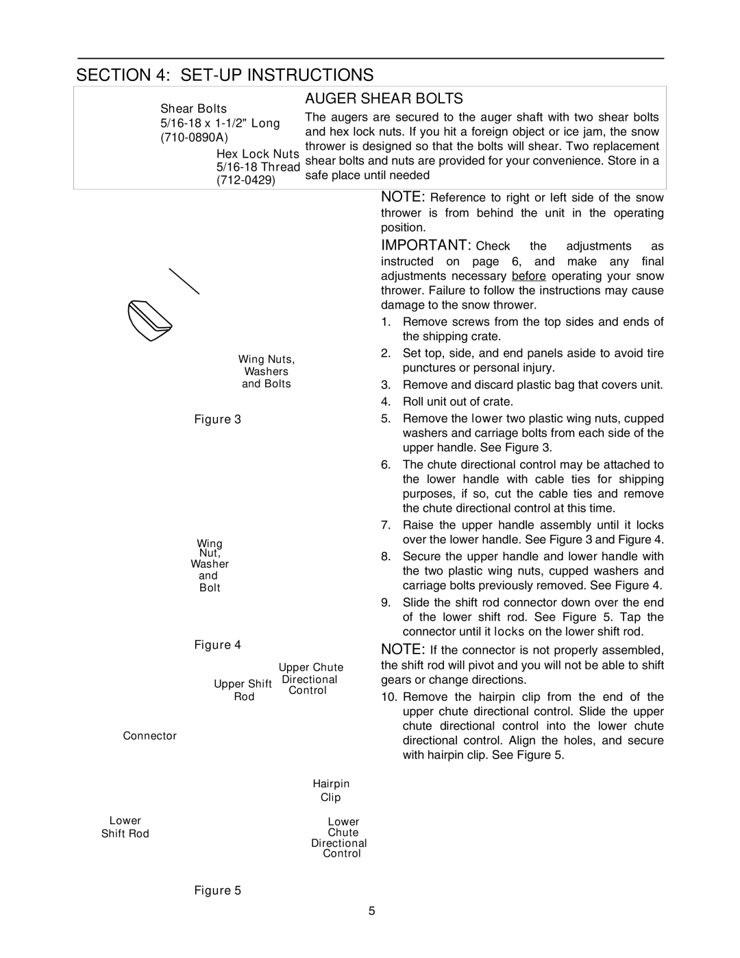
AUGER SHEAR BOLTS
Shear Bolts | The augers are secured to the auger shaft with two shear bolts | ||
and hex lock nuts. If you hit a foreign object or ice jam, the snow | |||
thrower is designed so that the bolts will shear. Two replacement | |||
Hex Lock Nuts | |||
| safe place until needed | ||
|
| ||
|
| ||
| NOTE: Reference to right or left side of the snow | ||
| thrower is from behind the unit in the operating | ||
| position. | ||
| IMPORTANT: Check the adjustments as | ||
| instructed on page 6, and make any final | ||
| adjustments necessary before operating your snow | ||
| thrower. Failure to follow the instructions may cause | ||
| damage to the snow thrower. | ||
| 1. | Remove screws from the top sides and ends of | |
|
| the shipping crate. | |
Wing Nuts, | 2. | Set top, side, and end panels aside to avoid tire | |
| punctures or personal injury. | ||
Washers |
| ||
and Bolts | 3. | Remove and discard plastic bag that covers unit. | |
| 4. | Roll unit out of crate. | |
Figure 3 | 5. | Remove the lower two plastic wing nuts, cupped | |
|
| washers and carriage bolts from each side of the | |
|
| upper handle. See Figure 3. | |
| 6. | The chute directional control may be attached to | |
|
| the lower handle with cable ties for shipping | |
|
| purposes, if so, cut the cable ties and remove | |
|
| the chute directional control at this time. | |
| 7. | Raise the upper handle assembly until it locks | |
Wing |
| over the lower handle. See Figure 3 and Figure 4. | |
Nut, | 8. | Secure the upper handle and lower handle with | |
Washer |
| the two plastic wing nuts, cupped washers and | |
and |
| ||
| carriage bolts previously removed. See Figure 4. | ||
Bolt |
| ||
| 9. | Slide the shift rod connector down over the end | |
|
| of the lower shift rod. See Figure 5. Tap the | |
|
| connector until it locks on the lower shift rod. | |
|
| Figure 4 |
| NOTE: If the connector is not properly assembled, |
|
|
| Upper Chute | the shift rod will pivot and you will not be able to shift |
|
| Upper Shift | Directional | gears or change directions. |
|
| Rod | Control | 10. Remove the hairpin clip from the end of the |
|
|
| ||
|
|
|
| upper chute directional control. Slide the upper |
Conne |
| or |
| chute directional control into the lower chute |
ct |
| directional control. Align the holes, and secure | ||
|
|
|
| |
|
|
|
| with hairpin clip. See Figure 5. |
|
|
| Hairpin |
|
|
|
| Clip |
|
Lower | Lower |
| ||
Shift Rod | Chute |
| ||
|
|
| Directional |
|
|
|
| Control |
|
|
| Figure 5 |
|
|
5