AUGER BELTS
NOTE: It is necessary to remove both belts in order to change either one. If changing just one belt, be cer- tain to check the condition of the other belt (model 600/610E has only one auger belt).
1.Remove the plastic belt cover on the front of the engine by removing the two
Belt |
Cover |
Screws |
Figure 24
2.Drain the gasoline from the snow thrower, or place a piece of plastic under the gas cap.
3.Tip the snow thrower up and forward so that it rests on the housing.
4.Remove six
5.Roll the front and rear auger belts off the engine pulley. See Figure 25.
Rear Auger | Drive |
|
Belt | Belt | Engine |
|
| Pulley |
Idler | Front Auger | |
Belt | ||
Pulley |
|
|
Engine | Idler |
|
Pulley |
| |
Pulley |
|
|
Figure 25
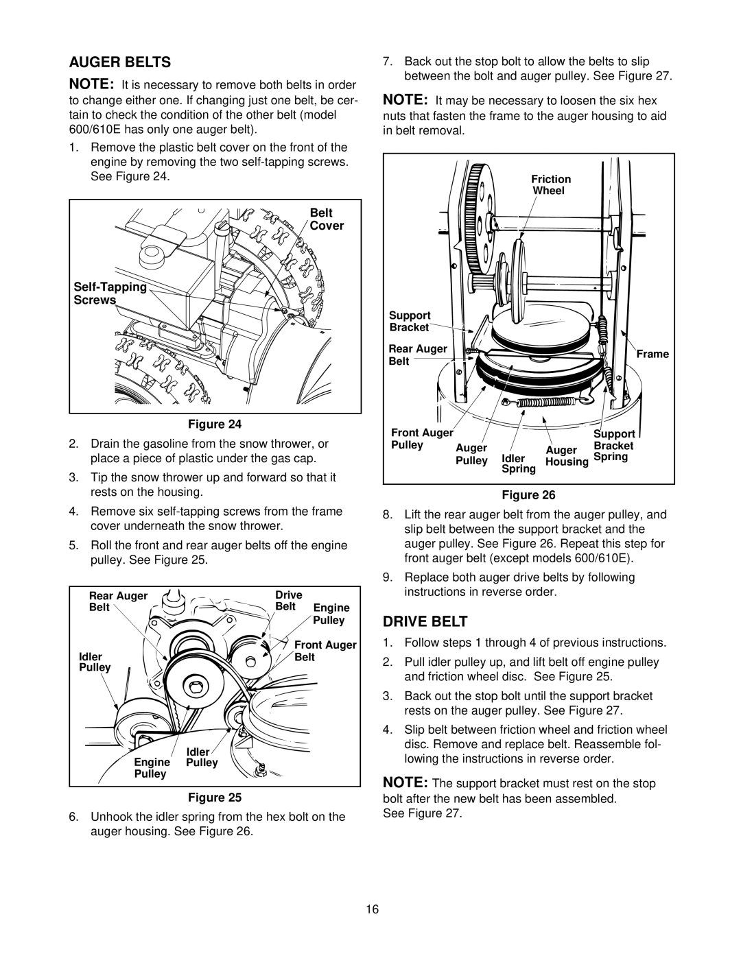
6.Unhook the idler spring from the hex bolt on the auger housing. See Figure 26.
7.Back out the stop bolt to allow the belts to slip between the bolt and auger pulley. See Figure 27.
NOTE: It may be necessary to loosen the six hex nuts that fasten the frame to the auger housing to aid in belt removal.
|
| Friction |
| |
|
| Wheel |
| |
Support |
|
|
|
|
Bracket |
|
|
|
|
Rear Auger |
|
|
| Frame |
Belt |
|
|
| |
|
|
|
| |
Front Auger |
|
|
| Support |
Pulley | Auger | Idler | Auger | Bracket |
| Pulley | Housing | Spring | |
| Spring |
| ||
Figure 26
8.Lift the rear auger belt from the auger pulley, and slip belt between the support bracket and the auger pulley. See Figure 26. Repeat this step for front auger belt (except models 600/610E).
9.Replace both auger drive belts by following instructions in reverse order.
DRIVE BELT
1.Follow steps 1 through 4 of previous instructions.
2.Pull idler pulley up, and lift belt off engine pulley and friction wheel disc. See Figure 25.
3.Back out the stop bolt until the support bracket rests on the auger pulley. See Figure 27.
4.Slip belt between friction wheel and friction wheel disc. Remove and replace belt. Reassemble fol- lowing the instructions in reverse order.
NOTE: The support bracket must rest on the stop bolt after the new belt has been assembled.
See Figure 27.
16