assembly and installation
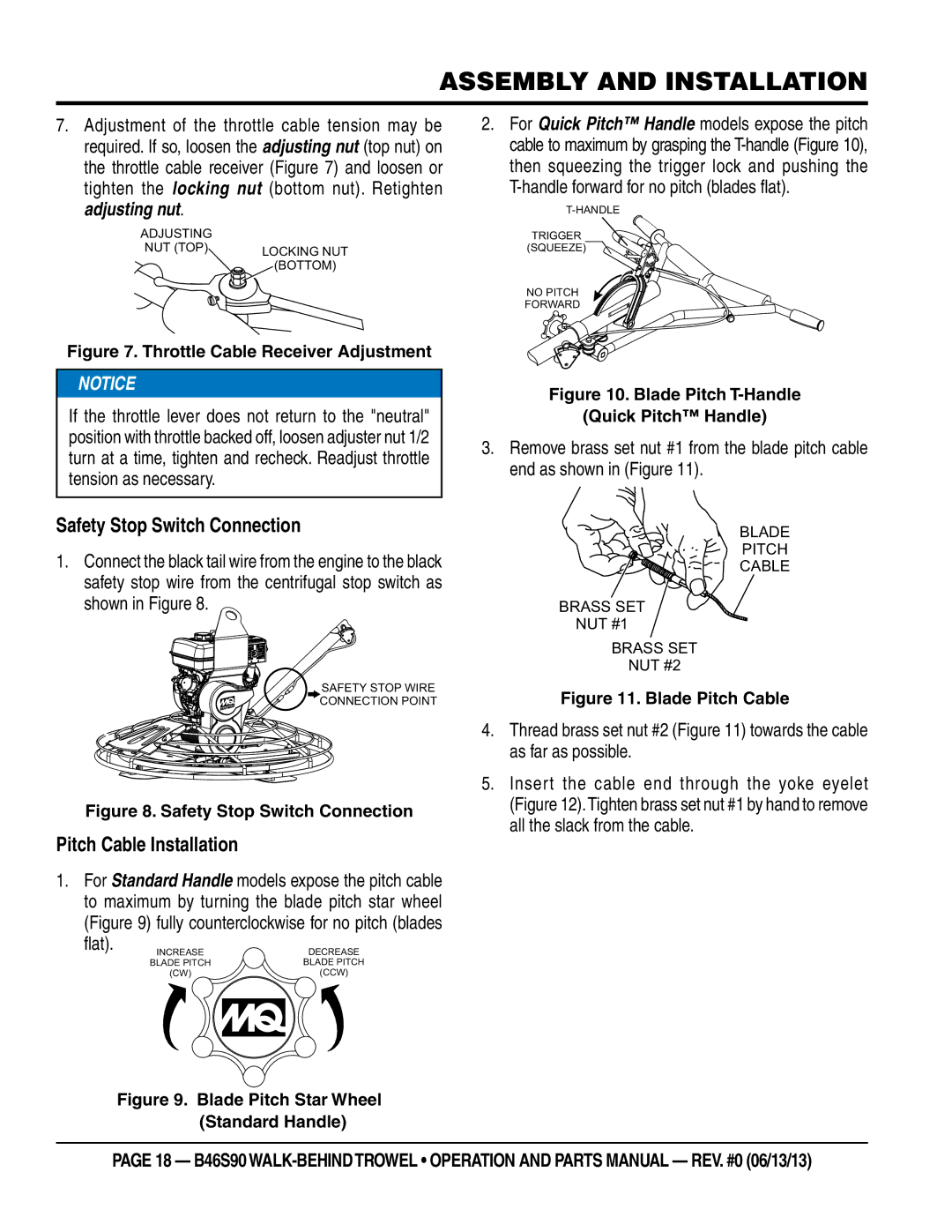
7.Adjustment of the throttle cable tension may be required. If so, loosen the adjusting nut (top nut) on the throttle cable receiver (Figure 7) and loosen or tighten the locking nut (bottom nut). Retighten adjusting nut.
ADJUSTING
NUT (TOP) LOCKING NUT (BOTTOM)
Figure 7. Throttle Cable Receiver Adjustment
![]()
![]() NOTICE
NOTICE
If the throttle lever does not return to the "neutral" position with throttle backed off, loosen adjuster nut 1/2 turn at a time, tighten and recheck. Readjust throttle tension as necessary.
Safety Stop Switch Connection
1.Connect the black tail wire from the engine to the black safety stop wire from the centrifugal stop switch as shown in Figure 8.
SAFETY STOP WIRE
CONNECTION POINT
Figure 8. Safety Stop Switch Connection
Pitch Cable Installation
1.For Standard Handle models expose the pitch cable to maximum by turning the blade pitch star wheel (Figure 9) fully counterclockwise for no pitch (blades
flat). | INCREASE | DECREASE |
| ||
| BLADE PITCH | BLADE PITCH |
| (CW) | (CCW) |
Figure 9.
2.For Quick Pitch™ Handle models expose the pitch cable to maximum by grasping the
T-handle forward for no pitch (blades flat).
TRIGGER
(SQUEEZE)
NO PITCH
FORWARD
Figure 10. Blade Pitch T-Handle
(Quick Pitch™ Handle)
3.Remove brass set nut #1 from the blade pitch cable end as shown in (Figure 11).
BLADE
PITCH
CABLE
BRASS SET
NUT #1
BRASS SET
NUT #2
Figure 11. Blade Pitch Cable
4.Thread brass set nut #2 (Figure 11) towards the cable as far as possible.
5.Insert the cable end through the yoke eyelet (Figure 12).Tighten brass set nut #1 by hand to remove all the slack from the cable.
page 18 — b46S90