Manuals
/
Multiquip
/
Lawn and Garden
/
Portable Generator
Multiquip
DCA-70USI50 Hz — NAME PLATE AND DECALS ASSY, Nameplate And Decals Assy
Models:
DCA-70USI
1
78
82
82
Download
82 pages
8.52 Kb
75
76
77
78
79
80
81
82
<
>
Troubleshooting
Specification
Install
Parts list
DCA-70USI50 Hz —TRAILERWIRING DIAGRAM
Warranty
Dimension
Maintenance
Connecting Loads
Symptom
Page 78
Image 78
DCA-70USI
(50 Hz) — NAME PLATE AND DECALS ASSY.
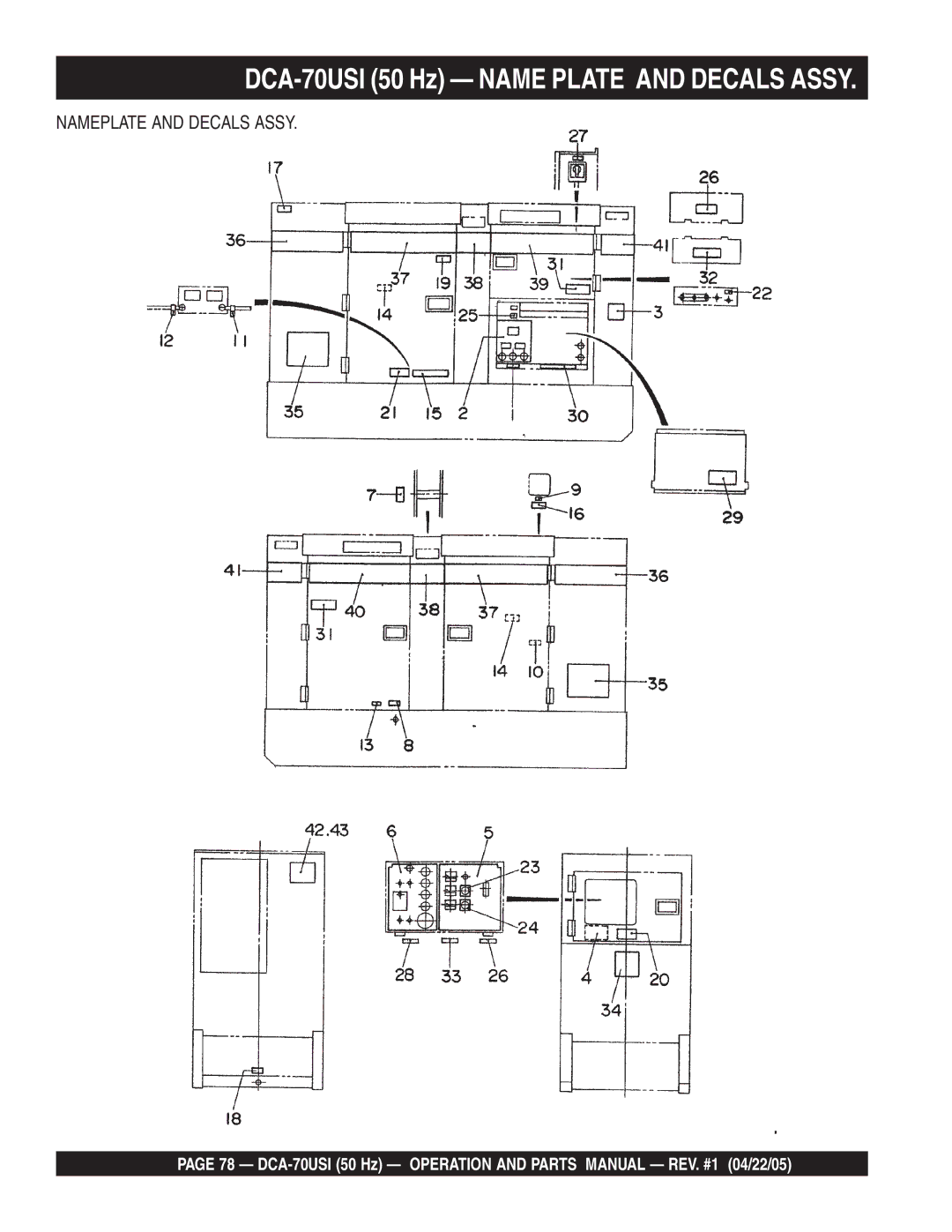
NAMEPLATE AND DECALS ASSY.
PAGE 78 —
DCA-70USI
(50 Hz) — OPERATION AND PARTS MANUAL — REV. #1 (04/22/05)
Page 77
Page 79
Page 78
Image 78
Page 77
Page 79
Contents
MODEL DCA-70USI
PARTS LIST NO. M2900000314
OPERATION AND PARTS MANUAL
ULTRA-SILENTTM SERIES
Page
SERVICE DEPARTMENT
HERES HOW TO GET HELP
NUMBER ON-HAND WHEN CALLING
WARRANTYDEPARTMENT
Specification and part
TABLE OF CONTENTS
MQ POWER DCA-70USI50HZ ULTRA-SILENTGENERATOR
ISUZU FF- 4BG1T ENGINE
please supply the following information
PARTS ORDERING PROCEDURES
When ordering parts
Extra Discounts
Table 2. Engine Specifications
DCA-70USI50 Hz — SPECIFICATIONS
Table 1. Generator Specifications
1500 rpm
TABLE 3. DIMENSIONS
DCA-70USI50 Hz — DIMENSIONS TOP, SIDE AND FRONT
Figure 1. Dimensions
Dimension ft. mm
SAFETY MESSAGE ALERT SYMBOLS
DCA- 70USI 50 Hz — SAFETY MESSAGE ALERT SYMBOLS
HAZARD SYMBOLS
Ultra Silent Generator
CAUTION - ACCIDENTAL STARTING
DCA- 70USI 50 Hz — SAFETY MESSAGE ALERT SYMBOLS
WARNING - ROTATING PARTS
CAUTION - OVER-SPEEDCONDITIONS
General Safety
DCA-70USI50 Hz — RULES FOR SAFE OPERATION
DANGER - READTHIS MANUAL
Generator Grounding
Electrical Safety
DCA-70USI50 Hz — RULES FOR SAFE OPERATION
DANGER - ELECTROCUTION HAZARDS
DANGER - EXPLOSION HAZARDS
Maintenance Safety
Battery Safety
DCA-70USI50 Hz — RULES FOR SAFE OPERATION
Towing &Transporting Safety
Emergencies
DCA-70USI50 Hz — RULES FOR SAFE OPERATION
DCA-70USI50 Hz — GENERATOR DECALS
Figure 2. Generator Decals
DCA-70USI50 Hz — GENERATOR DECALS
Figure 3. Generator Decals Cont inued
DCA-70USI50 Hz — INSTALLATION
Figure 4.Typical Generator Grounding Application
Indoor Installation
DCA-70USI50 Hz — INSTALLATION
Outdoor Installation
CAUTION - EXHAUST HAZARD
Engine Operating Panel
DCA-70USI50 Hz — GENERAL INFORMATION
Generator
Generator Control Panel
Figure 5. Major Components
DCA-70USI50 Hz — MAJOR COMPONENTS
Table 4. Generator Major Components
1Muffler Assembly 2 Engine Assembly
NOTE PAGE
DCA-70USI50 Hz — GENERATOR CONTROL PANEL
Figure 6. Generator Control Panel
DCA-70USI50 Hz — ENGINE OPERATING PANEL
Figure 7. Engine Operating Panel
DCA-70USI50 Hz — ENGINE OPERATING PANEL
11.Auto On/Off Engine Controller MPEC –
Output Terminal Familiarization
Figure 8. Output Terminal Panel
Output Terminal Panel
Figure 11. Voltage Regulator Control Knob
100VAC GFCI Receptacles
Figure 9. G.F.C.I. Receptacle
Figure 10. 100/100V Twist-Lock
Blower Fan
Connecting Loads
Figure 13. Connecting Loads Over Current Relay
Figure 15. Blower Fan Fuse
Three Phase Load
Single Phase Load
Table 5. Power Factor By Load
DCA-70USI50 Hz — LOAD APPLICATION
Voltage Selector Switch Locking Button
Voltage Selector Switch
Figure 16. Voltage Selector Switch
DCA-70USI50 Hz — GENERATOR OUTPUTS
139VThree Phase Position
How to Read the OutputTerminal Gauges
Figure 17. Voltage Selector Switch
DCA-70USI50 Hz — GAUGE READING
UVWO Terminal Output Voltages
Three-PhasePosition
Figure 25. Voltage Selector Switch 240/139V
3Ø 220/127 Output Terminal Lug Voltages
1Ø 200V/100V Output Terminal Lug Voltages
Figure 27. Voltage Selector Switch 480/277V
3Ø 440/254 Output Terminal Lug Voltages
Figure 28. Output Terminal Lugs
Lubrication Oil
DCA-70USI50 Hz — PRE-SETUP
Circuit Breakers
Fuel Check
WARNING - RESPIRATORY HAZARDS
DCA-70USI50 Hz — PRE-SETUP
Refueling Procedure
Figure 34. Fueling the Generator
Table 10. Coolant Capacity
Cleaning the Radiator
Air Cleaner
Fan Belt Tension
Figure 38. Battery Connections
Battery
Battery Cable Installation
CAUTION - BATTERY SERVICING SAFETY
Before Starting
Figure 41. Voltage Selector Switch
Figure 44. MPEC Control Switch Manual Position
CAUTION - LETHAL EXHAUST HAZARD
Figure 45. Engine Running LED ON
Figure 48.Voltage Adjust Control Knob
Figure 51. Coolant Temperature Gauge
Figure 46. Frequency Meter Hz
Shutdown Procedure
Starting Auto Mode
CAUTION - BACKUP GENERATOR USE
WARNING - AUTO MODE MAINTENANCE
Air Cleaner with Dust Indicator
DCA-70USI50 Hz — MAINTENANCE
TABLE 12. INSPECTION/MAINTENANCE
Service Daily
Check Oil Level
Cleaning the Fuel Strainer
Air Removal
Replacing Oil Filter
DCA-70USI50 Hz —TRAILERMAINTENANCE
Trailer Maintenance
Brakes
DCA-70USI50 Hz —TRAILERMAINTENANCE
Brake Adjustment
Hydraulic Surge Brakes
TireWear/Inflation
Tires/Wheels/Lug Nuts
CAUTION - EYESIGHT HAZARD
Suspension
Figure 59. Wheel Lug Nuts Tightening Sequence
DCA-70USI50 Hz —TRAILERMAINTENANCE
Lug Nut Torque Requirements
Table 16. Tire Torque Requirements
DCA-70USI50 Hz —TRAILERWIRING DIAGRAM
Figure 60. Trailer/Towing Vehicle Wiring Diagram
DCA-70USI50 Hz — GENERATORWIRING DIAGRAM
Figure 61. Generator Wiring Diagram
DCA-70USI50 Hz — ENGINEWIRING DIAGRAM
Figure 62. Engine Wiring Diagram
Check output voltage using a voltmeter
DCA-70USI50 Hz —TROUBLESHOOTINGGENERATOR
TABLE 17. GENERATOR TROUBLESHOOTING
Is wiring connection loose?
SYMPTOM
DCA-70USI50 Hz —TROUBLESHOOTINGENGINE CONTROLLER
TABLE 18. ENGINE CONTROLLER TROUBLESHOOTING MPEC
POSSIBLE PROBLEM
Items Found In the “Items Number” Column
EXPLANATION OF CODE IN REMARKS COLUMN
Items Found In the “Remarks” Column
notice
DCA-70USI50 Hz — SUGGESTED SPARE PARTS
DCA-70USI50 Hz WHISPERWATTGENRATOR
W/ISUZU FF4BG1T DIESEL ENGINE 1TO 3 UNITS
DCA-70USI50 HZ — GENERATOR ASSY
GENERATOR ASSY
PART NAME
DCA-70USI50 Hz — GENERATOR ASSY
PART NO
REMARKS
DCA-70USI50 Hz — CONTROL BOX ASSY
CONTROL BOX ASSY
PART NAME
DCA-70USI50 Hz — CONTROL BOX ASSY
PART NO
REMARKS
DCA-70USI50 Hz — CONTROL BOX ASSY. CONT
PART NO
DCA-70USI50 Hz — CONTROL BOX ASSY. CONT
CONTROL BOX ASSY
PART NAME
DCA-70USI50 Hz — ENGINE AND RADIATOR ASSY
ENGINE AND RADIATOR ASSY
PART NO
DCA-70USI50 Hz — ENGINE AND RADIATOR ASSY
ENGINE AND RADIATOR ASSY
PART NAME
DCA-70USI50 Hz — ENGINE AND RADIATOR ASSY. CONT
PART NO
DCA-70USI50 Hz — ENGINE AND RADIATOR ASSY. CONT
ENGINE AND RADIATOR ASSY
PART NAME
DCA-70USI50 Hz — OUTPUTTERMINAL ASSY
OUTPUT TERMINAL ASSY
PART NAME
DCA-70USI50 Hz — OUTPUTTERMINAL ASSY
PART NO
REMARKS
DCA-70USI50 Hz — BATTERY ASSY
BATTERY ASSY
PART NO
DCA-70USI50 Hz — BATTERY ASSY
BATTERY ASSY
PART NAME
DCA-70USI50 Hz — MUFFLER ASSY
MUFFLER ASSY
PART NO
DCA-70USI50 Hz — MUFFLER ASSY
MUFFLER ASSY
PART NAME
DCA-70USI50 Hz — FUEL TANK ASSY
FUEL TANK ASSY
PART NO
DCA-70USI50 Hz — FUEL TANK ASSY
FUEL TANK ASSY
PART NAME
DCA-70USI50 Hz — ENCLOSURE #1 ASSY
ENCLOSURE #1 ASSY
PART NO
DCA-70USI50 Hz — ENCLOSURE #1 ASSY
ENCLOSURE #1 ASSY
PART NAME
DCA-70USI50 Hz — ENCLOSURE #1 ASSY. CONT
PART NAME
DCA-70USI50 Hz — ENCLOSURE #1 ASSY. CONT
PART NO
0010120050
DCA-70USI50 Hz — ENCLOSURE #2 ASSY
ENCLOSURE #2 ASSY
PART NO
DCA-70USI50 Hz — ENCLOSURE #2 ASSY
ENCLOSURE #2 ASSY
PART NAME
DCA-70USI50 Hz — RUBBER SEALS ASSY
RUBBER SEALS ASSY
PART NO
DCA-70USI50 Hz — RUBBER SEALS ASSY
RUBBER SEALS ASSY
PART NAME
DCA-70USI50 Hz — NAME PLATE AND DECALS ASSY
NAMEPLATE AND DECALS ASSY
PART NO
DCA-70USI50 Hz — NAME PLATE AND DECALS ASSY
NAMEPLATE AND DECALS ASSY
PART NAME
2.ToobtainaReturnMaterialAuthorization
TERMS AND CONDITIONS OF SALE — PARTS
SPECIAL EXPEDITING SERVICE
Effective:October 1,
NOTE PAGE
SERVICE DEPARTMENT
HERES HOW TO GET HELP
NUMBER ON-HAND WHEN CALLING
WARRANTYDEPARTMENT