HDA-SERIES
Proposition 65 Warning
Page
Table of Contents
Best Deal! Order via Internet Dealers Only
Parts Ordering Procedures
Order via Fax Dealers Only
Machine layout, location of components, checking of engine
Training Checklist
Training Checklist
Read Operator’s Manual completely
Daily PRE-OPERATION Checklist
Daily PRE-OPERATION Checklist
Do not follow directions
Safety Message Alert Symbols
Property, or the surrounding
Always wear approved eye and hearing protection
You do not follow instructions
Rules for Safe Operation
Safety
Rules for Safe Operation
Emergencies
Maintenance Safety
Always know the location of the nearest and first aid kit
Operation and Safety Decals
Operation and Safety Decals
Top View SideView
Specifications Trowel
Specifications Trowel
Height Lifting Hook 34.5 in 876.2 mm
Honda GX340K1QA2 Honda GX390K1QA2
Specifications Engines
Specifications Engines
Model
General Information
General Information
HDA-SERIES Walk-Behind Trowels
Controls and Components
Guard Ring- NEVER! put hands or feet inside guard ring
Basic Engine
Basic Engine
Initial Servicing
Feed the throttle cable through the cable housing
Assembly and Installation
Assembly and Installation
HandleTube Installation All Models
Safety Stop SwitchWire
Handle Height Adjustment
Tighten cable clamp screw and swivel stop screw
Blade Pitch Cable
Engine Oil Check
PRE-INSPECTION
PRE-INSPECTION
Before Starting
Controls
Lifting Bail Option
Initial START-UP
Initial START-UP
Lifting the Trowel Onto a Slab Auxiliary Lifting Tube
Place the Choke Lever in the Closed position
Test the Safety Stop Switch
Operation
Operation
PitchingThe Blades Quick-PitchHandle
Equipment
Never place your feet or hands inside
Parts while operating this equipment
Guard rings while starting or operating this
Combo Blades
Options
Options
Clip-On Float Blades Optional
Lifting Bail
Trowel Arm Adjustment Fixture
Maintenance
Maintenance
Maintenance Schedule
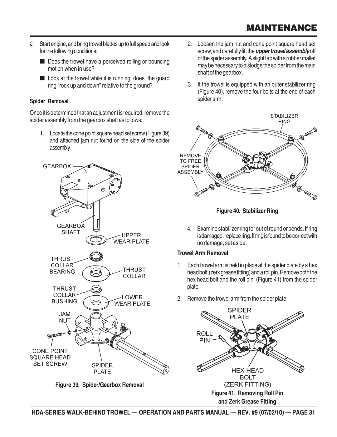
Trowel Arm Removal
Spider Removal
Remove the trowel arm from the spider plate
Trowel Arm Flatness Test
Bronze Bushings Trowel Blade Removal
Locking Nut
Trowel Arm Adjustment
AdjustmentBolt
Re-Assembly
Engine Engine Oil Change
Testing
Changing a Blade Belt Removal and Replacement
Before removing the blades
Troubleshooting Trowel
Troubleshooting Trowel
Troubleshooting Trowel
Troubleshooting Engine
Troubleshooting Engine
Xxxxx only Not Used on
Explanation of Codes
Description
Suggested Spare Parts
ARM 16-1/2
Nameplate and Decals
Decal QUICK-PITCH Handle
Decal PRE-LOAD Indicator
Service Dept
Decal Power Trowel
Detail B See Detail a
Standard Handle ASSY. OLD Style
GRIP, Handle
HANDLE, Adjustable
Wire ASSY., Safety Stop Switch
HOUSING, Cable
Standard Handle ASSY. NEW Style
WHEEL, Hand Handle
QUICK-PITCH Handle ASSY. OLD Style
DECAL, Q.P. Warning
CONNECTOR, QP Control ARM
BLOCK, QP Adjustment
DECAL, Latch Warning
QUICK-PITCH Handle ASSY. OLD Style
DECAL, Arrow
NUT, QP Trim Control Adjust
SCREW, QP Trim Adjustment
HOUSING, Throttle Cable
QUICK-PITCH Handle ASSY. NEW Style
PIN, Support Block 3/8 X
Blade Spider Assy
Bushing
Wear Ring
Flange Bearing
Wear Plate
Gearbox & Engine Mounts Assy
BEARING, CONE, Timken
SEAL, OIL TCM 10172VTB-H
FLANGE, Countershaft
BEARING, CUP, Timken
ENGINE, 11 HP Honda Assy
Part Name QTY Remarks
ENGINE, 13 HP Honda Assy
Includes Item W/%
Guard Ring Assy
9178
Part Name QTY. Remarks
Detail a
Stabilizer Ring Assy
1237
WASHER, LOCK, 5/16 MED
Blades & ARM ADJ. Fixture ASSY. Options
7281
0202 Hhcs 5/16-18X1 Ring 0201
1434
1162 a
Lifting Bail ASSY. Option
2360
10229 Hhcs 5/16-24X1 0161 a
Honda GX340K1QA2 AIR Cleaner Assy
COLLAR, AIR Cleaner
ELEMENT, AIR Cleaner
COVER, AIR Cleaner
GROMMET, AIR Cleaner
Honda GX340K1QA2 Camshaft Assy
LIFTER, Valve
SPRING, Weight Return
ROD, Push
ARM, Valve Rocker
Honda GX340K1QA2 Piston Assy
Ring SET, Ppiston
BOLT, Connecting ROD
Ring SET, PISTON- Standard
Ring SET, PISTON- OS
Honda GX340K1QA2 Crankcase Cover Assy
GASKET, Case Cover
WEIGHT, Governor
HOLDER, Governor Weight
PIN, Governor Weight
Honda GX340K1QA2 Crankshaft Assy
90756ZE2600 KEY 961006207000
WEIGHT, Balancer
13310ZE3601
13351ZE3010
Honda GX340K1QA2 Cylinder Barrel Assy
NUT, Flange 10MM
USE from Engine
SHAFT, Governor ARM
BOLT, Drain Plug
Honda GX340K1QA2 Cylinder Head Assy
TUBE, Breather
CLIP, Valve Guide
GASKET, Cylinder Head
COVER, Head
Honda GX340K1QA2 FAN Cover Assy
Shroud
CLIP, Wire Harness
CLIP, Tube
COVER, FAN *R8* Bright RED
Honda GX340K1QA2 Flywheel Assy
Flywheel
FAN, Cooling
Honda GX340K1QA2 Fuel Tank Assy
GASKET, Fuel Filler CAP
RUBBER, Supporter 107MM
JOINT, Fuel Tank
Tank Fuel *T34* Simpson Blue
Honda GX340K1QA2 Ignition Coil Assy
GROMMET, Wire
Coil ASSEMBLY, Ignition
WIRE, Stop Switch 430MM
Honda GX340K1QA2 Carburetor Assy
Includes Items W/%
Gasket SET
Valve SET, Float
Float SET
Honda GX340K1QA2 Carburetor Assy
25 + 9430520122
Honda GX340K1QA2 Muffler Assy
PIPE, EX
Muffler
PROTECTOR, Muffler
PROTECTOR, EX. Pipe
Honda GX340K1QA2 Recoil Starter Assy
SPRING, Starter Return
PULLEY, Recoil Starter
RATCHET, Starter
SPRING, Friction
Honda GX340K1QA2 Control Assy
No ART Work
SPRING, Throttle Return
ARM, Governor
ROD, Governor
SPRING, Governor
Honda GX340K1QA2 Labels Assy
MARK, OIL Alert E
Emblem
LABEL, Caution
MARK, Choke External
Honda GX390K1QA2- AIR Cleaner Assy
90009ZE2003
Collar B, AIR Cleaner Includes Items W
WINGNUT, Tool BOX Setting
17231ZE3W01
Honda GX390K1QA2- Camshaft Assy
VALVE, Exhaust
VALVE, Intake
Honda GX390K1QA2- Piston Assy
Piston Standard
Ring SET, Piston STD
Ring SET, Piston OS 0.25, OPT
Ring SET, Piston OS 0.50, OPT
Honda GX390K1QA2- Crankcase Cover Assy
Includes Items W/ #
Honda GX390K1QA2- Crankshaft Assy
90745ZE2600 KEY 91001ZF6003
13310ZF6W10
BEARING, Radial Ball 6207S
Honda GX390K1QA2- Cylinder Barrel Assy
91353671003
91203952771
3415ZH7003
Honda GX390K1QA2- Cylinder Head Assy
Spark Plug BPR6ES NGK
GUIDE, Valve OS Optional
GUIDE, EX. Valve OS Optional
GASKET, Cylinder Head Cover
Honda GX390K1QA2- FAN Cover Assy
COVER, FAN *NH1*, Black
19610ZE3010ZB
Honda GX390K1QA2- Flywheel Assy
PULLEY, Starter Screen Grid
Honda GX390K1QA2- Fuel Tank Assy
91353671003 Ring 13.5X1.5 Arai 9405008000
RUBBER, Supporter 107 MM
17510ZE3010ZB
TANK, Fuel *NH1* Black
Honda GX390K1QA2- Ignition Coil Assy
30500ZF6W01
Honda GX390K1QA2- Carburetor Assy
JET, Main #92
PLATE, Lever Setting
Screw SET, Drain Includes Items W/#
Screw SET B Includes Items W/#
Honda GX390K1QA2- Muffler Assy
PIPE, Exhaust
PROTECTOR, Exhaust Pipe
Honda GX390K1QA2- Recoil Starter Assy
90008ZE2003
28400ZE3W01ZB
28410ZE3W01ZB
28462ZV7003
Honda GX390K1QA2- Control Assy
NUT, SELF-LOCK 6MM
BASE, Control
Honda GX390K1QA2- Gasket KIT Assy
GASKET, Exhaust Pipe
GASKET, Insulator
Gasket KIT
Honda GX390K1QA2- Labels Assy
87530ZF6W10
87521ZF6W01
87576ZH7W00
Terms and Conditions of Sale Parts
Page
HERE’S HOW to GET Help