|
|
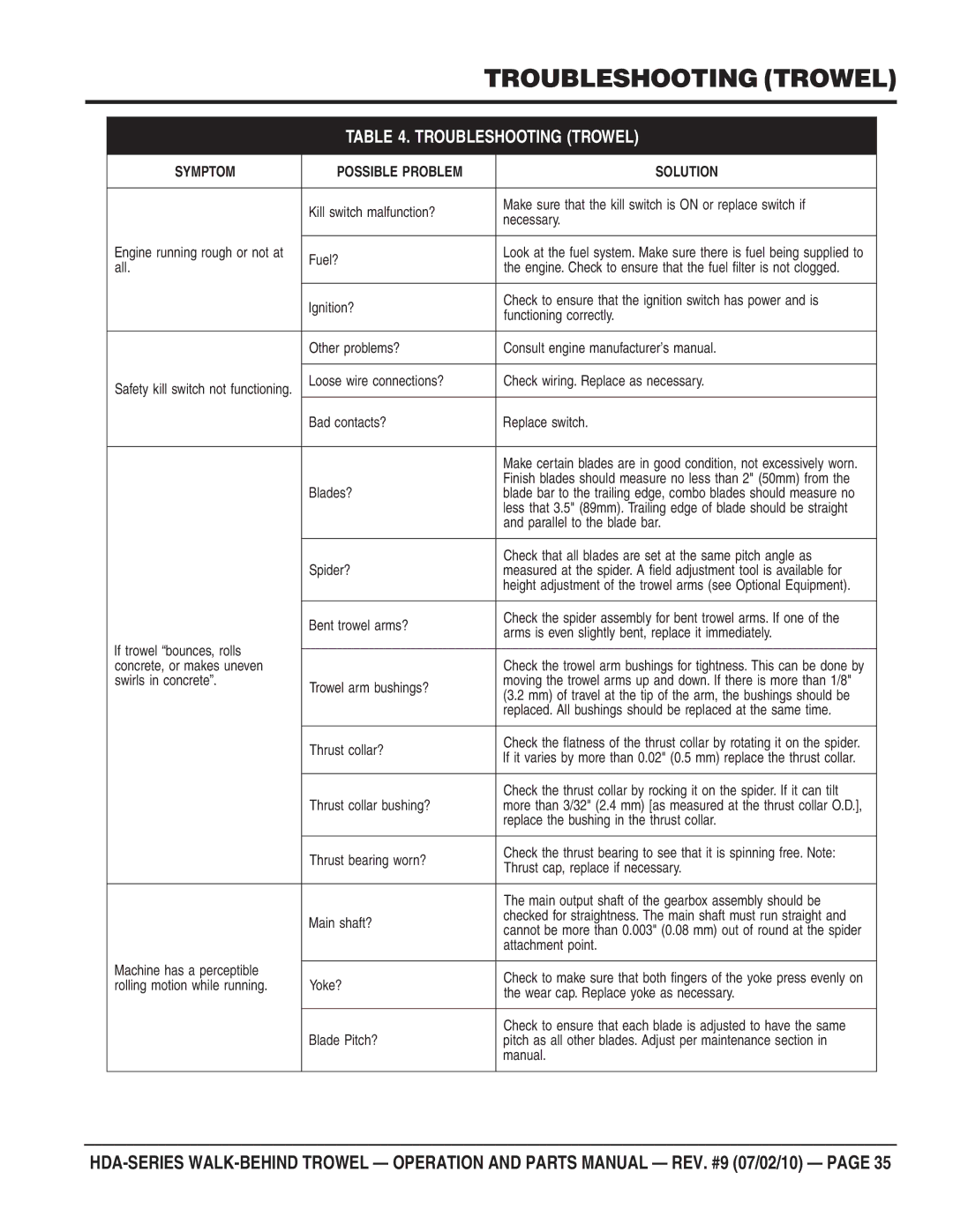
| TROUBLESHOOTING (TROWEL) | ||
|
|
|
|
| |
|
| TABLE 4. TROUBLESHOOTING (TROWEL) |
| ||
|
|
|
|
|
|
| SYMPTOM | POSSIBLE PROBLEM |
| SOLUTION |
|
|
|
|
|
|
|
|
| Kill switch malfunction? |
| Make sure that the kill switch is ON or replace switch if |
|
|
|
| necessary. |
| |
|
|
|
|
| |
|
|
|
|
|
|
| Engine running rough or not at | Fuel? |
| Look at the fuel system. Make sure there is fuel being supplied to |
|
| all. |
| the engine. Check to ensure that the fuel filter is not clogged. |
| |
|
|
|
| ||
|
|
|
|
|
|
|
| Ignition? |
| Check to ensure that the ignition switch has power and is |
|
|
|
| functioning correctly. |
| |
|
|
|
|
| |
|
|
|
|
|
|
|
| Other problems? |
| Consult engine manufacturer’s manual. |
|
|
|
|
|
|
|
| Safety kill switch not functioning. | Loose wire connections? |
| Check wiring. Replace as necessary. |
|
|
|
|
|
| |
|
| Bad contacts? |
| Replace switch. |
|
|
|
|
|
|
|
|
|
|
| Make certain blades are in good condition, not excessively worn. |
|
|
|
|
| Finish blades should measure no less than 2" (50mm) from the |
|
|
| Blades? |
| blade bar to the trailing edge, combo blades should measure no |
|
|
|
|
| less that 3.5" (89mm). Trailing edge of blade should be straight |
|
|
|
|
| and parallel to the blade bar. |
|
|
|
|
|
|
|
|
| Spider? |
| Check that all blades are set at the same pitch angle as |
|
|
|
| measured at the spider. A field adjustment tool is available for |
| |
|
|
|
| height adjustment of the trowel arms (see Optional Equipment). |
|
|
|
|
|
|
|
|
| Bent trowel arms? |
| Check the spider assembly for bent trowel arms. If one of the |
|
|
|
| arms is even slightly bent, replace it immediately. |
| |
|
|
|
|
| |
| If trowel “bounces, rolls |
|
|
|
|
|
|
| Check the trowel arm bushings for tightness. This can be done by |
| |
| concrete, or makes uneven |
|
|
| |
| swirls in concrete”. | Trowel arm bushings? |
| moving the trowel arms up and down. If there is more than 1/8" |
|
|
|
| (3.2 mm) of travel at the tip of the arm, the bushings should be |
| |
|
|
|
|
| |
|
|
|
| replaced. All bushings should be replaced at the same time. |
|
|
|
|
|
|
|
|
| Thrust collar? |
| Check the flatness of the thrust collar by rotating it on the spider. |
|
|
|
| If it varies by more than 0.02" (0.5 mm) replace the thrust collar. |
| |
|
|
|
|
| |
|
|
|
|
|
|
|
|
|
| Check the thrust collar by rocking it on the spider. If it can tilt |
|
|
| Thrust collar bushing? |
| more than 3/32" (2.4 mm) [as measured at the thrust collar O.D.], |
|
|
|
|
| replace the bushing in the thrust collar. |
|
|
|
|
|
|
|
|
| Thrust bearing worn? |
| Check the thrust bearing to see that it is spinning free. Note: |
|
|
|
| Thrust cap, replace if necessary. |
| |
|
|
|
|
| |
|
|
|
|
|
|
|
|
|
| The main output shaft of the gearbox assembly should be |
|
|
| Main shaft? |
| checked for straightness. The main shaft must run straight and |
|
|
|
| cannot be more than 0.003" (0.08 mm) out of round at the spider |
| |
|
|
|
|
| |
|
|
|
| attachment point. |
|
| Machine has a perceptible |
|
|
|
|
|
|
| Check to make sure that both fingers of the yoke press evenly on |
| |
| rolling motion while running. | Yoke? |
|
| |
|
| the wear cap. Replace yoke as necessary. |
| ||
|
|
|
|
| |
|
|
|
|
|
|
|
|
|
| Check to ensure that each blade is adjusted to have the same |
|
|
| Blade Pitch? |
| pitch as all other blades. Adjust per maintenance section in |
|
|
|
|
| manual. |
|
|
|
|
|
|
|
