

 6
6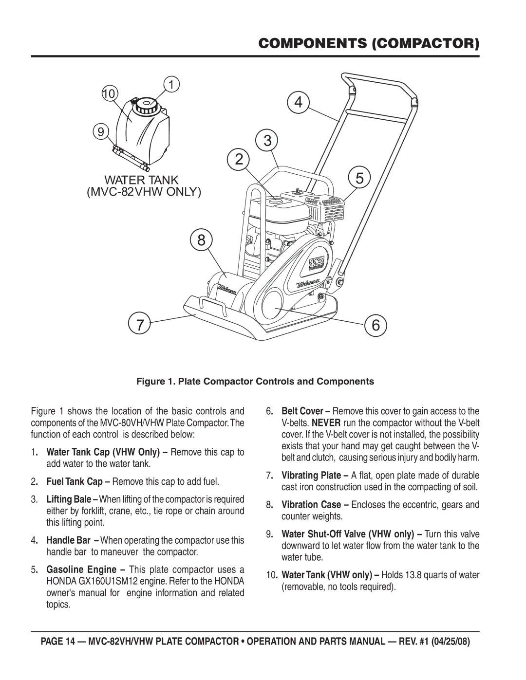
MVC-82VH, MVC-82VHW specifications
The Multiquip MVC-82VHW and MVC-82VH are advanced walk-behind vibratory plate compactors, designed for efficient soil compaction in various construction and landscaping applications. These models combine robust engineering with cutting-edge technologies, making them ideal for both professionals and contractors.The MVC-82VHW is powered by a reliable Honda GX160 engine, delivering impressive performance with minimal vibration. This model stands out due to its built-in water tank system, which allows for the effective compaction of asphalt while reducing the risk of material sticking to the base plate. Furthermore, the MVC-82VHW features an easy-to-use hand throttle, allowing operators to adjust the engine speed on the fly to suit specific job requirements.
On the other hand, the MVC-82VH is equipped with a durable Robin Subaru engine, known for its impressive torque and fuel efficiency. Both models feature a heavy-duty, high-quality steel frame that is designed to withstand the rigors of daily use on tough job sites. Their compact design allows for easy transportation and maneuverability, even in confined spaces.
A key characteristic of both models is their high-frequency vibration technology. This feature ensures optimal compaction in a variety of soil types, from granular to cohesive materials. The MVC-82s provide an operating frequency that allows them to achieve excellent compaction depth, making them a valuable asset for construction sites, road repairs, and landscaping tasks.
User comfort is also a significant consideration in the design of the MVC-82 series. The machines are outfitted with padded handles, which reduce operator fatigue during prolonged use. Additionally, the low center of gravity design enhances stability and control, allowing operators to handle challenging terrains with confidence.
In summary, the Multiquip MVC-82VHW and MVC-82VH compactors are exceptional machines that deliver superior performance and durability. With powerful engines, high-frequency vibration technology, and user-centric design features, these models are ideal for maximizing efficiency in compaction tasks across various job sites. They represent an investment in quality and reliability, setting a standard in the compacting equipment market. Whether for asphalt or soil compaction, these machines make the job easier and more efficient.