AA-2D CHASSIS
SERVICE MANUAL
TRINITRON COLOR TV
SPECIFICATIONS
Supplied Accessories
Optional Accessory
Design and specifications are subject to change without notice
TABLE OF CONTENTS
SAFETY-RELATED COMPONENT WARNING
DISASSEMBLY
SET-UP ADJUSTMENTS
SAFETY CHECK-OUT
HOW TO FIND A GOOD EARTH GROUND
Fig. A. Using an AC voltmeter to check AC leakage
LEAKAGE TEST
Precautions
Using This Manual
Connecting and Installing the TV
Connecting and Installing the TV continued
Connecting and Installing the TV continued
Connecting and Installing the TV continued
VCR Connections
DBS Connections
Connecting and Installing the TV continued
Disconnect all power sources before making any connections
Disconnect all power sources before making any connections
Operating Video Equipment
Troubleshooting
Problem
Problem
Operating a Cable Box or DBS Receiver
SECTION DISASSEMBLY
2-2. CHASSIS ASSEMBLY REMOVAL
2-1. REAR COVER REMOVAL
KV-32S40/34SL40/34SL40C/32S45/KV-32V40/32V65/34VL65/34VL65C/35V65
2-3. SERVICE POSITION
2-4. CONTROL SWITCH REMOVAL
REMOVAL PROCEDURES
HOW TO HANDLE AN ANODE-CAP
WARNING -- Before removing anode cap
WARNING -- Before removing anode cap
K board
KV-32V65/34VL65
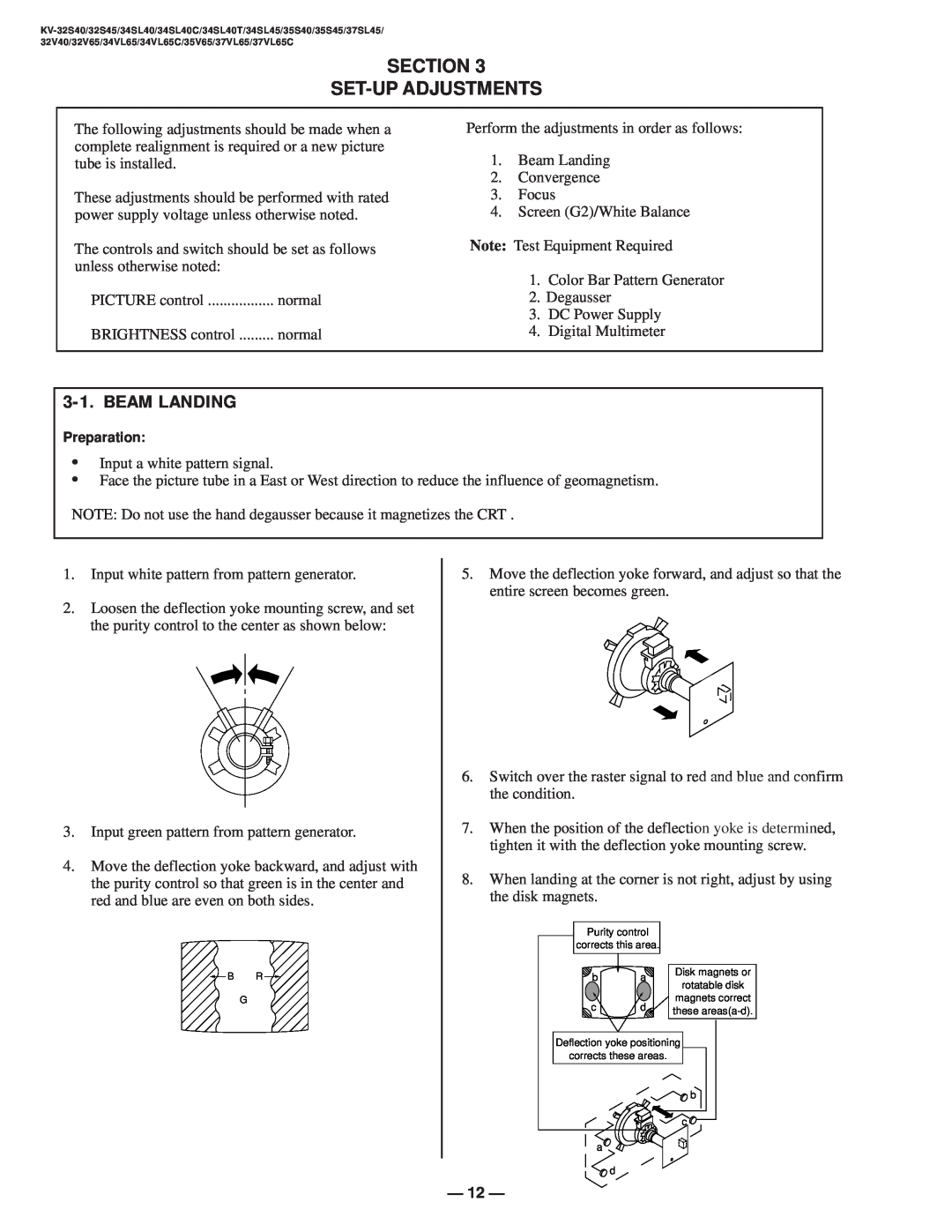
SECTION SET-UP ADJUSTMENTS
3-1. BEAM LANDING
Y Separation Axis Correction Magnet Adjustment
3-2. CONVERGENCE
1 Vertical and Horizontal Static Convergence
Operation of BMC Hexapole Magnet
3-5. WHITE BALANCE ADJUSTMENTS
2 Dynamic Convergence Adjustment
3-3. FOCUS
3-4. SCREEN G2
SECTION SAFETY RELATED ADJUSTMENTS
B+ VOLTAGE CONFIRMATION AND ADJUSTMENT
Step
Step
SECTION CIRCUIT ADJUSTMENTS
ELECTRICAL ADJUSTMENT BY REMOTE COMMANDER
1 Method of Setting the Service Adjustment Mode
3 Adjust Buttons and Indicator
4 Service Data
VP CXA2095S
AP CXA2021
MM1311/1313
Service Data cont
PI SDA9288
IC CXA2019
CC CXP8584a-011s
Service Data cont
5 Feature ID Map
ID-0
ID-1
SUB BRIGHT ADJUSTMENT SBRT
SUB CONTRAST ADJUSTMENT SCON
DISPLAY POSITION ADJUSTMENT DISP
SUB HUE, SUB COLOR ADJUSTMENT SHUE, SCOL
P BOARD ADJUSTMENTS
V. SIZE ADJUSTMENT VSIZ
V ANGLE VANG, V BOW VBOW, UPPER PIN UPIN AND LOW PIN LPIN ADJUSTMENTS
V. POSITION ADJUSTMENT VPOS
6-4. PRINTED WRING BOARDS AND SCHEMATIC DIAGRAMS
6-3. CIRCUIT BOARDS LOCATION
Page
rinted by CAMCAD A2dvblk
MICON Y/C/J TUNER VOL-CTL
AUDIO-AMP PIN-MOD V.DEF H.DEF AV-SW
FOR CHECK
VIDEO Y Y C
Page
Page
Page
Page
Page
Page
Page
6-5. SEMICONDUCTORS
SECTION EXPLODED VIEW
7-1. CHASSIS KV-32S40/34SL40/34SL40C/32S45/34SL45/34SL40T
REF.NO. PART NO
DESCRIPTION
7-2. CHASSIS KV-35S40/35S45/37SL45
REMARK
REF.NO. PART NO
DESCRIPTION
7-3. CHASSIS KV-32V40/32V65/34VL65/35VL65C/35V65/37VL65/37VL65C
REF.NO. PART NO
DESCRIPTION
REMARK
7-4. PICTURE TUBE KV-32V40/32V65/34VL65
REF.NO. PART NO
DESCRIPTION
REMARK
7-5. PICTURE TUBE KV-35VL65C/35V65/37VL65/37VL65C
113
103 112 110 108 109 105 104 117
REF.NO
ELECTRICAL PARTS LIST
PARTS LISTING TABLE OF CONTENTS
SECTION
Model
ELECTRICAL PARTS LIST FOR S SERIES
S SERIES
SECTION
REF.NO. PART NO
S SERIES A COMMON PARTS LISTING
DESCRIPTION
REMARK
DESCRIPTION
A S SERIES COMMON PARTS LISTING
CONNECTOR
DIODE
FERRITE BEAD
DESCRIPTION
REMARK
REF.NO. PART NO
REMARK
A S SERIES COMMON PARTS LISTING
REMARK
REMARK
REMARK
REMARK
DESCRIPTION
A S SERIES COMMON PARTS LISTING
SWITCH
REMARK
REMARK
TU102VARIANT SEE VARIANT PARTS LIST
TRANSFORMER
TUNER
CRYSTAL
ELECTRICAL PARTS LIST FOR V SERIES
V SERIES
SECTION
REF.NO. PART NO
A V SERIES COMMON PARTS LISTING
CONNECTOR
DIODE
DESCRIPTION
V SERIES A COMMON PARTS LISTING
FERRITE BEAD
CHIP CONDUCTOR
COIL
A V SERIES COMMON PARTS LISTING
REMARK
RESISTOR
REMARK
V SERIES A COMMON PARTS LISTING
REMARK
REMARK
A V SERIES COMMON PARTS LISTING
SWITCH
TRANSFORMER
TUNER
KV-32S40/34SL40/34SL40C
A BOARD VARIANT LIST KV-32S40/34SL40/34SL40C
REF.NO. PART NO
DESCRIPTION
KV-32S45/34SL45
A BOARD VARIANT LIST KV-32S45/34SL45
REF.NO. PART NO
DESCRIPTION
KV-35S40
A BOARD VARIANT LIST KV-35S40
REF.NO. PART NO
DESCRIPTION
KV-35S45/37SL45
A BOARD VARIANT LIST KV-35S45/37SL45
REF.NO. PART NO
DESCRIPTION
KV-34SL40T
A BOARD VARIANT LIST KV-34SL40T
REF.NO. PART NO
DESCRIPTION
KV-32V40
A BOARD VARIANT LIST KV-32V40
REF.NO. PART NO
DESCRIPTION
KV-34VL65C/34VL65/32V65CND
A BOARD VARIANT LIST KV-34VL65C/34VL65/32V65CND
REF.NO. PART NO
DESCRIPTION
KV-35V65CND/37VL65/37VL65C
A BOARD VARIANT LIST KV-35V65CND/37VL65/37VL65C
REF.NO. PART NO
DESCRIPTION
Page
COMPLETE PARTS LISTING B
CONNECTOR
A-1135-948-A B BOARD, COMPLETE
A-1135-949-A B BOARD, COMPLETE
B COMPLETE PARTS LISTING
TRANSISTOR
RESISTOR
CRYSTAL
COMPLETE PARTS LISTING C
CONNECTOR
A-1331-837-A C BOARD, COMPLETE
A-1331-843-A C BOARD, COMPLETE
Page
COMPLETE PARTS LISTINGG
DIODE
FUSE
FERRITE BEAD
GCOMPLETE PARTS LISTING
RELAY
TRANSFORMER
THERMISTOR
Page
Page
COMPLETE PARTS LISTING
DESCRIPTION
REF.NO. PART NO
DESCRIPTION
K COMPLETE PARTS LISTING
CONNECTOR
A-1380-585-A K BOARD, COMPLETE
CAPACITOR
COMPLETE PARTS LISTING P
REF.NO. PART NO
DESCRIPTION
P COMPLETE PARTS LISTING
CRYSTAL
REMARK
REF.NO. PART NO
COMPLETE PARTS LISTING
CONNECTOR
A-1394-905-A UV BOARD, COMPLETE
A-1394-906-A UV BOARD, COMPLETE
COMPLETE PARTS LISTING
DIODE
JACK
CHIP CONDUCTOR
COMPLETE PARTS LISTING
REMARK
REMARK
RESISTOR
COMPLETE PARTS LISTING
REMARK
REMARK
Page
COMPLETE PARTS LISTING
REF.NO. PART NO
DESCRIPTION
COMPLETE PARTS LISTING
CONNECTOR
A-1372-508-A WB BOARD, COMPLETE
CAPACITOR
ACCESSORIES AND PACKING MATERIALS
S SERIES
V SERIES
REF.NO. PART NO
Service Promotion Department
Sony Corporation
9-965-843-01
Sony Technology Center
SERVICE MANUAL
SUPPLEMENT-1
TRINITRON COLOR TV
AA-2D CHASSIS
Section 6 A Board Schematic Diagram S series Page
A Board Schematic Diagram V series Page Added Item
Service Promotion Department
Sony Corporation