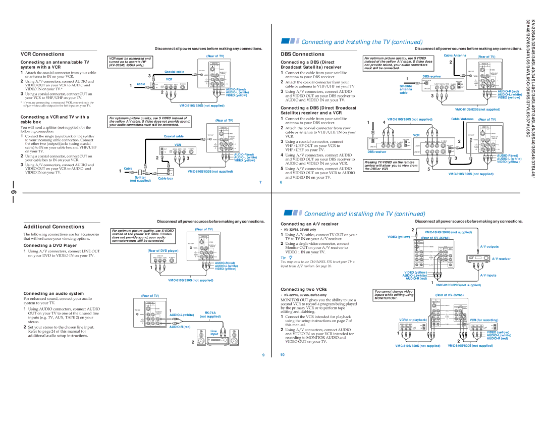
VCR Connections
Connecting an antenna/cable TV system with a VCR
1Attach the coaxial connector from your cable or antenna to IN on your VCR.
2Using A/V connectors, connect AUDIO and VIDEO OUT on your VCR to AUDIO and VIDEO IN on your TV.*
3Using a coaxial connector, connect OUT on your VCR to VHF/UHF on your TV.
*If you are connecting a monaural VCR, connect only the single white audio output to the left input on your TV.
Connecting a VCR and TV with a cable box
You will need a splitter (not supplied) for the following connection.
1Connect the single (input) jack of the splitter to your incoming cable connection. Connect the other two (output) jacks (using coaxial cable) to IN on your cable box and VHF/UHF on your TV.
2Using a coaxial connector, connect OUT on your cable box to IN on your VCR.
3Using A/V connectors, connect AUDIO and VIDEO OUT on your VCR to AUDIO and VIDEO IN on your TV.
— 6 —
Disconnect all power sources before making any connections.
VCR must be connected and |
|
|
|
| (Rear of TV) |
| |||
|
|
|
|
|
|
| |||
turned on to operate PIP |
|
|
|
| VIDEO IN |
| |||
|
|
|
|
| 1 | 2 |
| ||
|
|
|
| Coaxial cable | VHF/UHF | S VIDEO |
| ||
|
|
|
|
|
| ||||
|
|
|
|
| AUDIO OUT | ||||
|
| 3 |
|
|
|
| VIDEO | (VAR/FIX) |
|
|
|
| VCR |
|
|
| |||
|
|
|
|
| L |
| L | ||
|
|
|
|
|
|
| (MONO) |
| |
|
| Cable |
|
|
|
| AUDIO |
|
|
| 1 | OUT | AUDIO R AUDIO L VIDEO | S VIDEO | R |
| R | ||
|
| IN | LINE |
|
|
|
|
| |
|
| OUT |
|
|
|
| |||
|
|
|
| 2 |
|
|
|
| |
|
|
|
|
|
|
|
| ||
|
|
|
|
|
|
|
|
| VIDEO (yellow) |
|
|
|
|
|
|
| |||
For optimum picture quality, use S VIDEO instead of |
| (Rear of TV) | |||||||
the yellow A/V cable. S Video does not provide sound, | |||||||||
your audio connectors must still be connected. |
|
|
|
| |||||
|
|
|
|
|
|
|
| VIDEO IN | |
|
|
|
|
|
|
|
| 1 | 2 |
|
|
|
|
|
|
| VHF/UHF | S VIDEO | |
|
|
|
| Coaxial cable |
| ||||
|
|
|
|
|
| AUDIO OUT | |||
|
|
|
|
|
|
|
| VIDEO | (VAR/FIX) |
|
|
|
|
|
|
|
|
| |
|
|
|
|
| VCR |
| L | L | |
|
|
|
|
|
| AUDIO | |||
|
|
|
|
|
|
|
| (MONO) | |
|
|
|
| OUT | AUDIO R AUDIO L VIDEO | S VIDEO | R | R | |
|
|
|
|
|
| ||||
|
|
|
| IN | LINE |
|
|
|
|
|
|
|
| OUT |
|
|
| ||
|
|
| 2 |
|
| 3 |
| ||
|
|
|
|
|
| ||||
|
|
|
|
|
|
|
|
| VIDEO (yellow) |
1 | Cable |
|
|
| OUT |
| |||
|
|
|
|
| |||||
|
|
|
| IN |
| ||||
|
|
|
|
|
|
|
|
| |
|
| Splitter |
| Cable box |
|
|
|
| |
| (not supplied) |
|
|
|
|
|
| 7 | |
|
|
|
|
|
|
|
|
| |
Connecting and Installing the TV (continued) |
|
|
|
|
| 32V40/32V65/34VL65/34VL65C/35V65/37VL65/37VL65C | |||||
|
|
|
|
|
|
| |||||
|
|
|
| Disconnect all power sources before making any connections. |
|
| |||||
DBS Connections | For optimum picture quality, use S VIDEO | Cable/Antenna | (Rear of TV) |
|
| ||||||
|
|
|
|
| |||||||
Connecting a DBS (Direct | 2 |
|
|
|
|
|
| ||||
instead of the yellow A/V cable. S Video does |
|
| VIDEO IN |
|
| ||||||
Broadcast Satellite) receiver | not provide sound, your audio connectors |
|
|
| 1 | 2 |
|
| |||
must still be connected. |
|
|
|
|
|
| S VIDEO |
|
| ||
1 Connect the cable from your satellite |
|
|
|
|
|
| VHF/UHF |
|
|
| |
|
|
|
|
|
|
| (VAR/FIX) |
|
| ||
antenna to your DBS receiver. |
|
|
| DBS receiver |
|
|
|
| AUDIO OUT |
|
|
|
| 1 |
|
| VIDEO |
|
|
|
| ||
2 Attach the coaxial connector from your |
|
| SATELLITE IN |
| IN | L |
| L |
|
| |
|
|
| AUDIO R AUDIO L VIDEO S VIDEO | AUDIO |
|
|
| ||||
cable or antenna to VHF/UHF on your TV. |
| Satellite |
| VHF/UHF | (MONO) |
|
|
| |||
|
|
| OUT | R |
| R |
|
| |||
3 Using A/V connectors, connect AUDIO |
| antenna | LINE OUT |
|
|
|
|
|
|
| |
|
|
|
|
|
|
|
| ||||
| cable |
|
|
|
|
|
|
| |||
and VIDEO OUT on your DBS receiver to |
|
|
| 3 |
|
|
|
|
|
| |
|
|
|
|
|
|
| VIDEO (yellow) |
|
| ||
AUDIO and VIDEO IN on your TV. |
|
|
|
|
|
|
|
|
|
| |
|
|
|
|
|
|
|
|
|
|
| |
Connecting a DBS (Direct Broadcast |
|
|
|
|
|
| |||||
Satellite) receiver and a VCR |
|
|
|
|
|
| |||||
|
|
|
|
|
|
|
|
|
|
| |
1 Connect the cable from your satellite | 1 | Cable/Antenna | (Rear of TV) |
|
| ||||||
antenna to your DBS receiver. | 4 |
|
|
|
|
|
|
|
|
| |
2 Attach the coaxial connector from your |
|
|
|
|
|
|
| 1 | 2 |
|
|
|
|
|
|
|
|
|
| VIDEO IN |
|
| |
cable or antenna to VHF/UHF IN on your |
|
|
| VCR |
|
|
|
| S VIDEO |
|
|
VCR. |
|
|
|
|
| VHF/UHF |
|
|
|
| |
|
|
|
|
|
|
| AUDIO OUT |
|
| ||
SATELLITE IN |
|
|
|
|
|
|
| (VAR/FIX) |
|
| |
3 Using a coaxial connector, connect |
| VHF/UHF |
| S VIDEO | 2 | VIDEO |
|
|
|
| |
| AUDIO R AUDIO L VIDEO S VIDEO | IN | AUDIO R AUDIO L VIDEO |
|
|
|
|
| |||
VHF/UHF OUT on your VCR to | LINE OUT |
|
|
|
|
| L |
| L |
|
|
|
|
|
|
| AUDIO |
|
| ||||
|
|
| OUT | LINE IN | VHF/UHF |
| (MONO) |
|
|
| |
|
|
|
|
|
|
|
|
| |||
VHF/UHF on your TV. |
|
|
|
| IN |
| R |
| R |
|
|
DBS receiver |
|
| OUT |
|
|
|
| ||||
4 Using A/V connectors, connect AUDIO |
| LINE OUT |
|
|
|
|
|
|
| ||
|
|
|
| 3 |
|
|
|
|
| ||
and VIDEO OUT on your DBS receiver to | Pressing TV/VIDEO on the remote |
|
|
|
|
| |||||
AUDIO and VIDEO IN on your VCR. |
|
|
|
| VIDEO (yellow) |
|
| ||||
control will allow you to view from |
|
|
|
|
|
|
| ||||
5 Using A/V connectors, connect AUDIO |
|
|
|
|
|
|
| ||||
the DBS or VCR. |
| 5 |
|
|
|
|
|
|
| ||
and VIDEO OUT on your VCR to AUDIO |
|
|
|
|
|
| |||||
and VIDEO IN on your TV. |
|
|
|
|
|
|
|
|
|
|
|
8 |
|
|
|
|
|
|
|
|
|
|
|
![]()
![]() Connecting and Installing the TV (continued)
Connecting and Installing the TV (continued)
Additional Connections
The following connections are for accessories that will enhance your viewing options.
Disconnect all power sources before making any connections.
For optimum picture quality, use S VIDEO | (Rear of TV) | ||
instead of the yellow A/V cable. S Video |
|
|
|
does not provide sound, your audio |
| VIDEO IN | |
| 1 2 |
| |
connectors must still be connected. |
|
|
|
Connecting an A/V receiver
•
1 Using A/V cables, connect TV OUT on your |
TV to TV IN on your A/V receiver. |
Disconnect all power sources before making any connections.
| 2 | |
|
| |
VIDEO (yellow) |
| (Rear of |
Connecting a DVD Player
1Using A/V connectors, connect LINE OUT on your DVD to VIDEO IN on your TV.
| VHF/UHF | S VIDEO | |
|
| ||
|
| AUDIO OUT | |
| VIDEO | (VAR/FIX) | |
|
| ||
(Rear of DVD player) | L | L | |
(MONO) | |||
LINE OUT | AUDIO |
| |
R | R | ||
AUDIO R AUDIO L VIDEO S VIDEO | |||
|
| ||
|
| ||
1 |
| ||
| VIDEO (yellow) | ||
2 Using a single video connector, connect |
Monitor OUT on your A/V receiver to |
VIDEO 1 IN on your TV. |
Tip z
You may want to use CHANNEL FIX to set your TV's input to the A/V receiver. See page 26.
IN
VIDEO 1 VIDEO 3
S VIDEO | OUT |
TV | MONITOR AUDIO |
| (VAR/FIX) |
VIDEO |
|
L |
|
(MONO) |
|
AUDIO |
|
R |
|
|
VIDEO (yellow) ![]()
![]()
![]()
![]() A/V outputs
A/V outputs
A/V receiver
HRD
A/V inputs
1
Connecting an audio system
For enhanced sound, connect your audio system to your TV.
1Using AUDIO connectors, connect AUDIO OUT on your TV to one of the unused line inputs (e.g. TV, AUX, TAPE 2) on your stereo.
2Set your stereo to the chosen line input. Refer to page 24 of this manual for additional audio setup instructions.
(Rear of TV) |
|
| |
VIDEO IN |
|
| |
1 | 2 |
|
|
VHF/UHF | S VIDEO | 1 |
|
|
| ||
| AUDIO OUT | ||
| (VAR/FIX) | ||
VIDEO |
| ||
|
| (not supplied) | |
L |
|
| |
(MONO) |
|
|
|
AUDIO |
|
|
|
R |
|
|
|
|
|
| |
|
|
| Line |
|
|
| input |
|
| 2 | HRD |
Connecting two VCRs
•
MONITOR OUT gives you the ability to use a second VCR to record a program being played by the primary VCR or to perform tape editing and dubbing.
1Connect the VCR intended for playback using the setup instructions on page 7 of this manual.
2Using A/V connectors, connect AUDIO and VIDEO IN on your VCR intended for recording to MONITOR AUDIO and VIDEO OUT on your TV.
You cannot change video
inputs while editing using(Rear of
MONITOR OUT.
IN
VIDEO 1 VIDEO 3
|
| S VIDEO | OUT |
|
|
| TV | MONITOR AUDIO |
|
|
|
| (VAR/FIX) |
|
|
| VIDEO |
|
|
|
| L |
|
|
|
| (MONO) |
|
|
|
| AUDIO |
|
|
VCR (for playback) | R | VCR (for recording) | ||
| ||||
AUDIO R AUDIO L VIDEO | OUT | AUDIO R AUDIO L VIDEO | OUT | |
|
|
| ||
LINE | IN |
| LINE | IN |
OUT |
| IN | ||
1 |
| VIDEO (yellow) |
|
| |
| 2 | |
|
| |
9
10