MVH-406DSY— PLATE COMPACTOR COMPONENTS
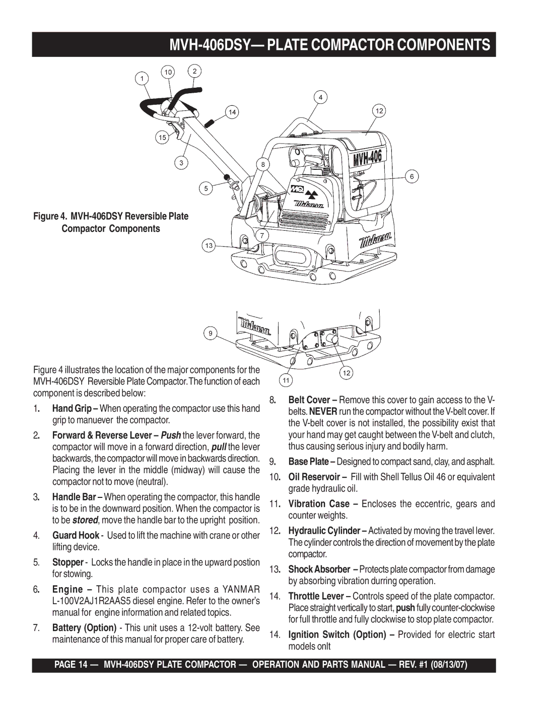
Figure 4. MVH-406DSY Reversible Plate
Compactor Components
Figure 4 illustrates the location of the major components for the MVH-406DSY Reversible Plate Compactor.The function of each component is described below:
1. Hand Grip – When operating the compactor use this hand grip to manuever the compactor.
2. Forward & Reverse Lever – Push the lever forward, the compactor will move in a forward direction, pull the lever backwards, the compactor will move in backwards direction. Placing the lever in the middle (midway) will cause the compactor not to move (neutral).
3. Handle Bar – When operating the compactor, this handle is to be in the downward position. When the compactor is to be stored, move the handle bar to the upright position.
4.Guard Hook - Used to lift the machine with crane or other lifting device.
5.Stopper - Locks the handle in place in the upward postion for stowing.
6. Engine – This plate compactor uses a YANMAR
7.Battery (Option) - This unit uses a
8. | Belt Cover – Remove this cover to gain access to the V- |
| belts.NEVER run the compactor without the |
| the |
| your hand may get caught between the |
| thus causing serious injury and bodily harm. |
9. | Base Plate – Designed to compact sand, clay, and asphalt. |
10. Oil Reservoir – Fill with Shell Tellus Oil 46 or equivalent grade hydraulic oil.
11. Vibration Case – Encloses the eccentric, gears and counter weights.
12. Hydraulic Cylinder – Activated by moving the travel lever. The cylinder controls the direction of movement by the plate compactor.
13. Shock Absorber – Protects plate compactor from damage by absorbing vibration durring operation.
14.Throttle Lever – Controls speed of the plate compactor. Place straight vertically to start, push fully
14.Ignition Switch (Option) – Provided for electric start models onlt
PAGE 14 —
