MAINTENANCE
See the engine manual supplied with
NOTE your machine for appropriate engine maintenance schedule and troubleshooting guide for problems.
At the front of the book (Page 6) there is a “Daily
CAUTION
Disconnect battery cables before attempting any service or maintenance on the
to cool before servicing. NEVER attempt any maintenance work on a hot! (muffler, radiator, etc.) trowel.
STX-SERIES — MAINTENANCE
MAINTENANCE PROCEDURES
Checking/Adjusting Trowel Speed
Because the two hydraulic drive motors operate independent of each other, the trowel speed between them may vary.If the unit’s steering is difficult to control, or if one spider is spinning noticeably faster or slower than the other, the trowel speed may need to be checked. It is also recommended that the trowel speed be checked at least once a year.
Trowel speed adjustment is a
Left Side Trowel Speed Adjustment
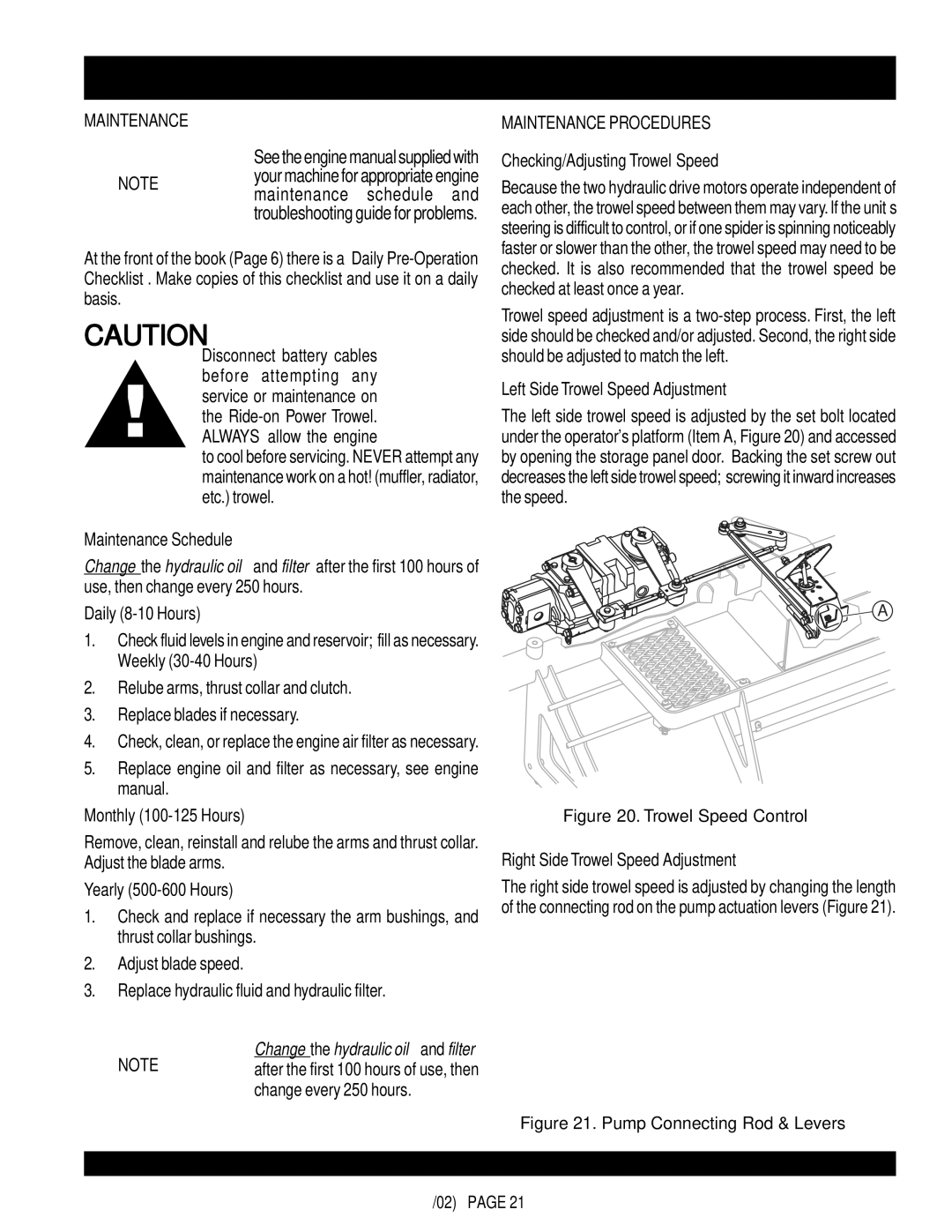
The left side trowel speed is adjusted by the set bolt located under the operator's platform (Item A, Figure 20) and accessed by opening the storage panel door. Backing the set screw out decreases the left side trowel speed; screwing it inward increases the speed.
Maintenance Schedule
Change the hydraulic oil and filter after the first 100 hours of use, then change every 250 hours.
Daily (8-10 Hours)
1.Check fluid levels in engine and reservoir; fill as necessary. Weekly
2.Relube arms, thrust collar and clutch.
3.Replace blades if necessary.
4.Check, clean, or replace the engine air filter as necessary.
5.Replace engine oil and filter as necessary, see engine manual.
Monthly
Remove, clean, reinstall and relube the arms and thrust collar. Adjust the blade arms.
Yearly (500-600 Hours)
1.Check and replace if necessary the arm bushings, and thrust collar bushings.
2.Adjust blade speed.
3.Replace hydraulic fluid and hydraulic filter.
Change the hydraulic oil and filter
NOTE after the first 100 hours of use, then change every 250 hours.
![]() A
A
Figure 20. Trowel Speed Control
Right Side Trowel Speed Adjustment
The right side trowel speed is adjusted by changing the length of the connecting rod on the pump actuation levers (Figure 21).
