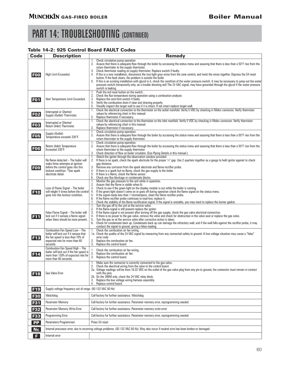
| Code | Description | | Remedy |
| | | 1. | Check circulation pump operation |
| | | 2. | Assure that there is adequate flow through the boiler by accessing the status menu and assuring that there is less than a 50°F rise from the |
| | | | return thermister to the supply thermister. |
| | | 3. | Check thermister reading on supply thermister. Replace switch if faulty. |
| F00 | High Limit Exceeded. | 4. | If this is a new installation, disconnect the two light grey wires from the zone control, and twist the wires together. Depress the S4 reset |
| | | | button. If the fault clears, the problem is outside the boiler |
| | | 5. | If this is an existing installation with glycol in it, check the condition of the water pressure switch. It may be necessary to jump out the water |
| | | | pressure switch (temporarily only, as a trouble shooting aid) The 24 VAC signal, may have grounded through the glycol if the water pressure |
| | | | switch is leaking. |
| | | 1. | Push the red reset button on the switch. |
| | | 2. | Check the flue temperature during operation using a combustion analyzer. |
| F01 | Vent Temperature Limit Exceeded. | 3. | Replace the vent limit switch if faulty. |
| | | 4. | Verify the combustion drain if clear and draining properly. |
| | | 5. | Visually inspect the target wall to see if it is intact. If not intact replace target wall. |
| | Interrupted or Shorted | 1. | Check the electrical connection to the thermister on the outlet manifold. Verify 5 VDC by checking in Molex connector. Verify thermister |
| F02 | | values by referencing chart in this manual. |
| Supply (Outlet) Thermister. | |
| | 2. | Replace thermister if necessary. |
| | |
| | Interrupted or Shorted | 1. | Check the electrical connection to the thermister on the inlet manifold. Verify 5 VDC by checking in Molex connector. Verify thermister |
| F03 | | values by referencing chart in this manual. |
| Return (Inlet) Thermister. | |
| | 2. | Replace thermister if necessary. |
| | |
| | Supply (Outlet) | 1. | Check circulation pump operation. |
| F05 | 2. | Assure that there is adequate flow through the boiler by accessing the status menu and assuring that there is less than a 50°F rise from the |
| Temperature exceeds 230°F. |
| | | return thermister to the supply thermister. |
| | | |
| F06 | | 1. | Check circulation pump operation. |
| Return (Inlet) Temperature | 2. | Assure that there is adequate flow through the boiler by accessing the status menu and assuring that there is less than a 50°F rise from the |
| | Exceeded 230°F. | | return thermister to the supply thermister. |
| | | 3. | Check direction of flow on boiler circulator. (See Piping Details in this manual.) |
| | | 1. | Watch the igniter through the observation window provided. |
| | No flame detected – The boiler will | 2. | If there is no spark, check the spark electrode for the proper ¼” gap. Use 2 quarters together as a gauge to hold ignitor against to check |
| | make three attempts at ignition | | gap distance. |
| F09 | before the control goes into this | 3. | Remove any corrosion from the spark electrode and flame rectifier probe. |
| | lockout condition. *See spark | 4. | If there is a spark but no flame, check the gas supply to the boiler. |
| | electrode detail. | 5. | If there is a flame, check the flame sensor. |
| | | 6. | Check any flue blockage or condensate blocks. |
| | | 1. | Monitor the gas pressure to the unit while in operation. |
| | | 2. | Assure that the flame is stable when lit. |
| | Loss of Flame Signal – The boiler | 3. | Check to see if the green light on the display module is out while the boiler is running. |
| F10 | will relight 4 times before the control | 4. | If the green light doesn’t come on or goes off during operation check the flame signal on the status menu. |
| | goes into this lockout condition. | 5. | If the signal reads less than 1 microampere, clean the flame rectifier probe. |
| | | 6. | If the flame rectifier probe continues to read low, replace it. |
| | | 7. | Check the stability of the flame rectification signal. If the signal is unstable, you may need to replace the burner gasket. |
| | | 1. | Turn the gas off to the unit at the service valve. |
| | | 2. | If the flame signal is still present replace the igniter. |
| | False Flame Signal – The boiler will | 3. | If the flame signal is not present after turning off the gas supply, check the gas valve electrical connection. |
| F11 | lock out if it senses a flame signal | 4. | If there is no power to the gas valve, remove the valve and check for obstruction in the valve seat or replace the gas valve. |
| | when there should be none present. | 5. | Turn the gas on at the service valve after corrective action is taken. |
| | | 6. | Check for condensate back up. Condensate back up can damage the refractory wall, and if the wall falls against the rectifier probe, it may |
| | | | conduct the signal to ground, giving a false reading. |
| | Combustion Fan Speed Low – The | 1. | Check the combustion air fan wiring. |
| | boiler will lock out if it senses that | 1a. | Check the quality of the 24 VAC signal by measuring from any connected safety to ground. A low voltage situation may cause a “false” |
| F13 | the fan speed is less than 70% of | | error code |
| expected rate for more than 60 | 2. | Replace the combustion air fan. |
| |
| | seconds. | 3. | Replace the control board. |
| | Combustion Fan Speed High – The | 1. | Check the combustion air fan wiring. |
| | boiler will lock out if the fan speed is |
| F14 | 2. | Replace the combustion air fan. |
| more than 130% of expected rate for | 3. | Replace the control board. |
| |
| | more than 60 seconds. | | |
| | | 1. | Make sure the connector is correctly connected to the gas valve. |
| | | 2. | Check the electrical wiring from the valve to the control board. |
| | | 2a. | Voltage readings will be from 18-22 VDC on the outlet of the gas valve plug from any pin to ground, the connector must remain in contact |
| F18 | Gas Valve Error | | with the pins. |
| | | 2b. | On the 399M only, check the 24 VAC relay block. |
| | | 3. | Replace the low voltage wiring harness assembly. |
| | | 4. | Replace control board. |
| | Supply voltage frequency out of range. (92-132 VAC 60 Hz) |
| F19 |
| | | |
| | Watchdog | Call factory for further assistance. Watchdog |
| F30 |
| | | |
| | Parameter Memory | Call factory for further assistance. Parameter memory error, reprogramming needed |
| F31 |
| | | |
| | Parameter Memory Write Error | Call factory for further assistance. Parameter memory write error |
| F32 |
| | | |
| | Programming Error | Call factory for further assistance. Parameter memory error, reprogramming needed |
| F33 |
| | | |
| | Parameters Programmed | Press S4 reset |
| PP |
| | | |
| | Internal processor error, due to incoming voltage problems. (92-132 VAC 60 Hz). May also occur if neutral wire has been broken or damaged. |
| Nc |
| | | |
| | Internal error | | |
| F | | |
| | | |