of cause of alarm. These circuits activate the alarm relay. Alarm circuits are active as long as power is applied to the
(a)Low Water Temperature; operated by low water temperature SWICHGAGE® .
(b)Air Damper Closed; operated by an external switch or by the Overspeed Relay circuit. This circuit is provided with a selector switch to allow the user to determine the source of the signal.
reset an external circuit when the Mode Selector is turned Off.
3-6 A903.
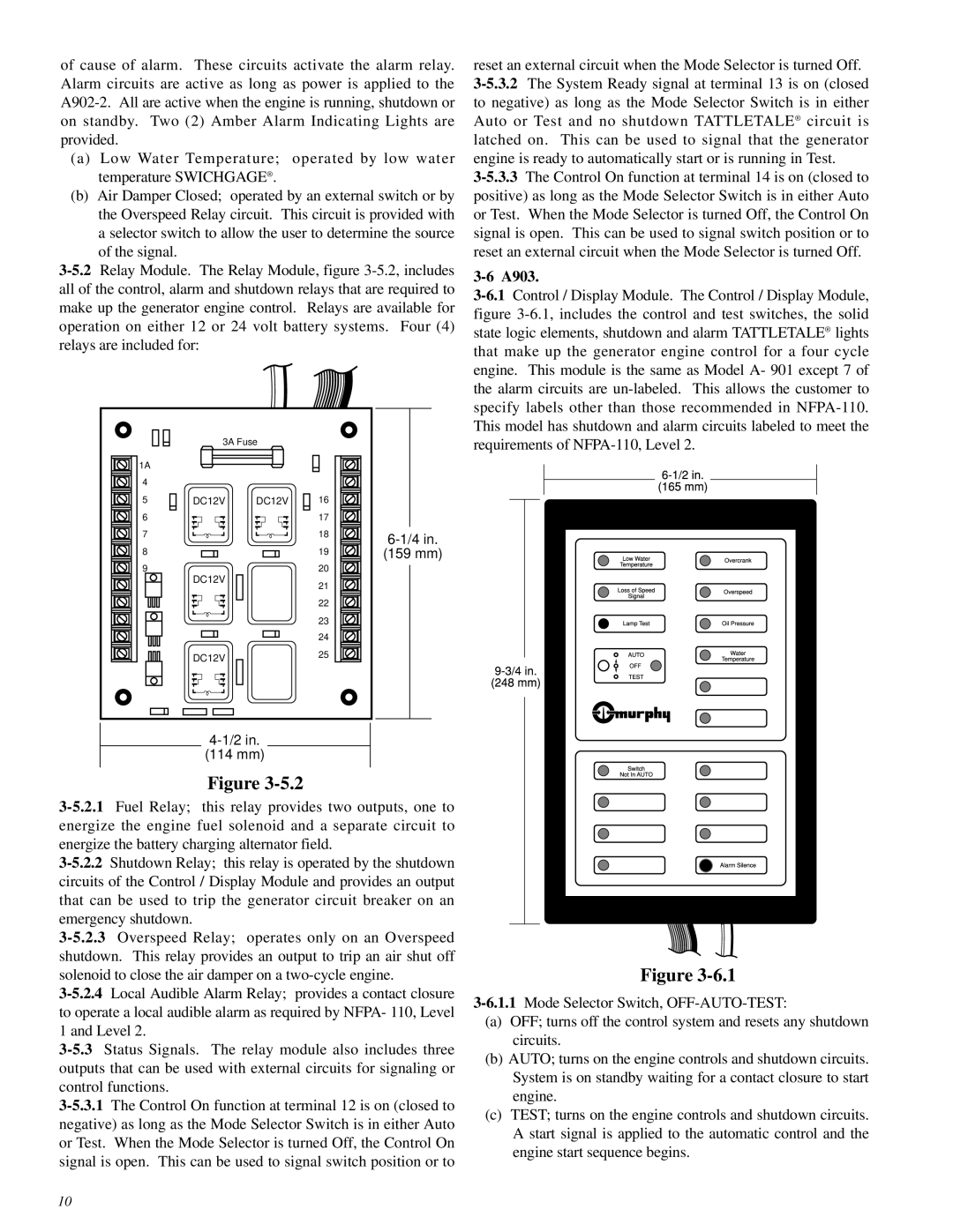
1A
4
5
6
7
8
9
3A Fuse
DC12V DC12V
DC12V
DC12V
16
17
18
19
20
21
22
23
24
25
(159 mm)
requirements of
(114 mm)
Figure
Figure
(a)OFF; turns off the control system and resets any shutdown circuits.
(b)AUTO; turns on the engine controls and shutdown circuits. System is on standby waiting for a contact closure to start engine.
(c)TEST; turns on the engine controls and shutdown circuits. A start signal is applied to the automatic control and the engine start sequence begins.
10