to operate a local audible alarm as required by NFPA- 110, Level 1 and Level 2.
on the flywheel ring gear.
(c)Auxiliary Crank Disconnect Circuit; this circuit, required by
(d)Overcrank circuit; will stop automatic cranking and indicate overcrank if engine fails to start after 3 attempts. The number of cranks are selectable for 1, 2, 3, 4 or 5 cycles before shutdown. The overcrank circuit may also be turned off so no overcrank shutdown occurs.
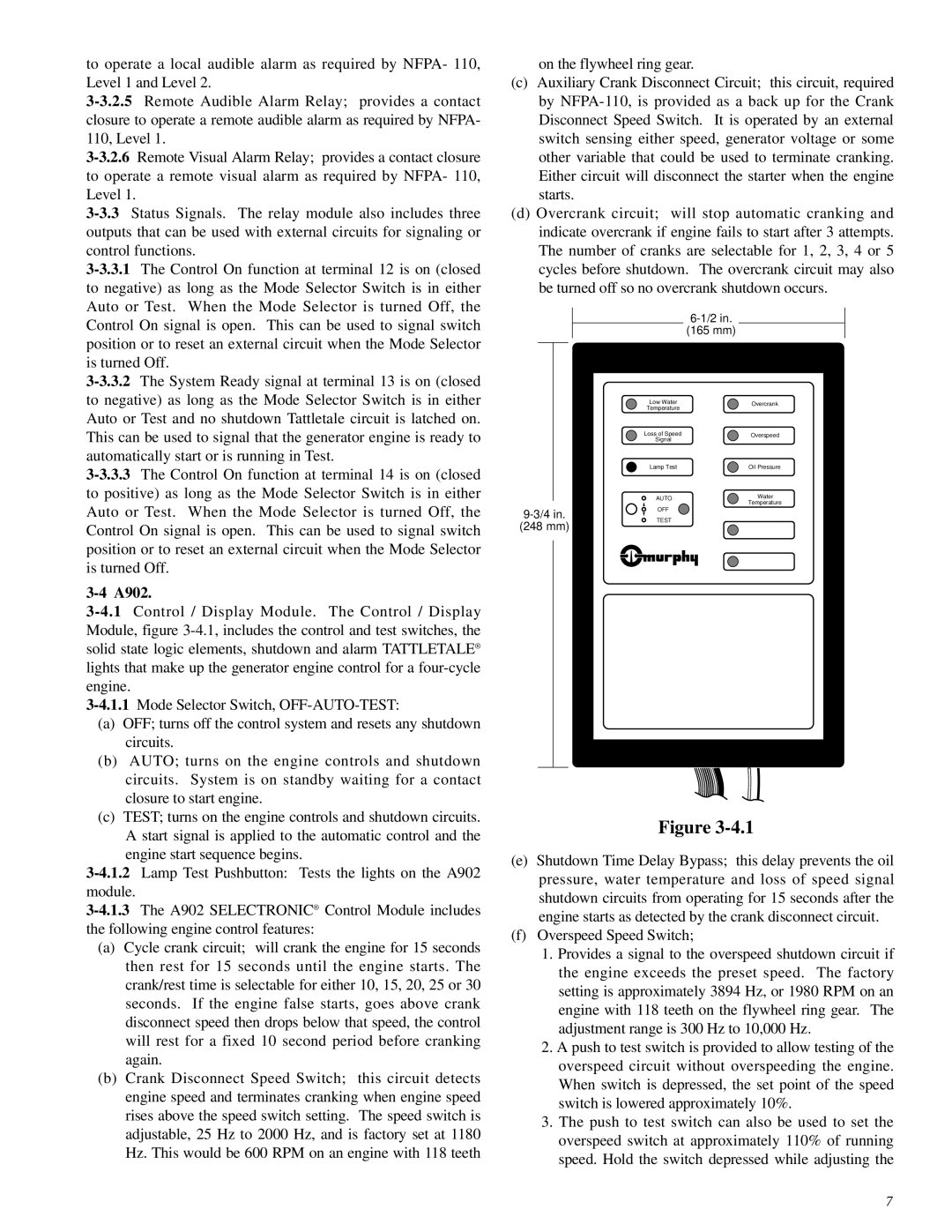
(165 mm)
Low Water | Overcrank | |
Temperature | ||
| ||
Loss of Speed | Overspeed | |
Signal | ||
| ||
Lamp Test | Oil Pressure | |
AUTO | Water | |
Temperature | ||
|
Auto or Test. When the Mode Selector is turned Off, the
OFF
Control On signal is open. This can be used to signal switch position or to reset an external circuit when the Mode Selector is turned Off.
3-4 A902.
(a)OFF; turns off the control system and resets any shutdown circuits.
(b)AUTO; turns on the engine controls and shutdown circuits. System is on standby waiting for a contact closure to start engine.
(c)TEST; turns on the engine controls and shutdown circuits.
A start signal is applied to the automatic control and the engine start sequence begins.
(248 mm)
TEST
Figure
(a)Cycle crank circuit; will crank the engine for 15 seconds then rest for 15 seconds until the engine starts. The crank/rest time is selectable for either 10, 15, 20, 25 or 30 seconds. If the engine false starts, goes above crank disconnect speed then drops below that speed, the control will rest for a fixed 10 second period before cranking again.
(b)Crank Disconnect Speed Switch; this circuit detects engine speed and terminates cranking when engine speed rises above the speed switch setting. The speed switch is adjustable, 25 Hz to 2000 Hz, and is factory set at 1180 Hz. This would be 600 RPM on an engine with 118 teeth
(e)Shutdown Time Delay Bypass; this delay prevents the oil pressure, water temperature and loss of speed signal shutdown circuits from operating for 15 seconds after the engine starts as detected by the crank disconnect circuit.
(f)Overspeed Speed Switch;
1.Provides a signal to the overspeed shutdown circuit if the engine exceeds the preset speed. The factory setting is approximately 3894 Hz, or 1980 RPM on an engine with 118 teeth on the flywheel ring gear. The adjustment range is 300 Hz to 10,000 Hz.
2.A push to test switch is provided to allow testing of the overspeed circuit without overspeeding the engine. When switch is depressed, the set point of the speed switch is lowered approximately 10%.
3.The push to test switch can also be used to set the overspeed switch at approximately 110% of running speed. Hold the switch depressed while adjusting the
7