4-1/2 in.
(114 mm)
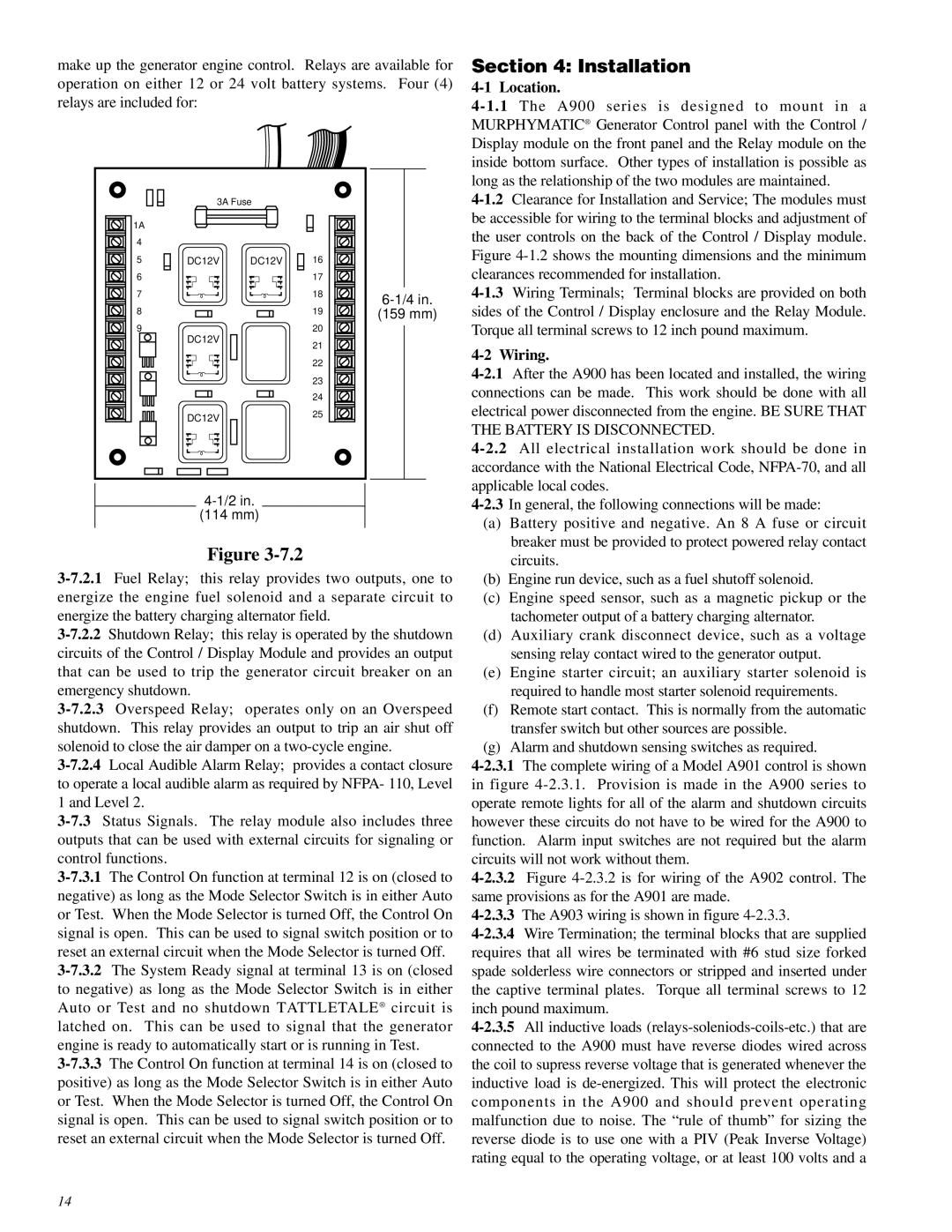
Figure 3-7.2
3-7.2.1Fuel Relay; this relay provides two outputs, one to energize the engine fuel solenoid and a separate circuit to energize the battery charging alternator field.
3-7.2.2Shutdown Relay; this relay is operated by the shutdown circuits of the Control / Display Module and provides an output that can be used to trip the generator circuit breaker on an emergency shutdown.
3-7.2.3Overspeed Relay; operates only on an Overspeed shutdown. This relay provides an output to trip an air shut off solenoid to close the air damper on a two-cycle engine.
3-7.2.4Local Audible Alarm Relay; provides a contact closure to operate a local audible alarm as required by NFPA- 110, Level 1 and Level 2.
3-7.3Status Signals. The relay module also includes three outputs that can be used with external circuits for signaling or control functions.
3-7.3.1The Control On function at terminal 12 is on (closed to negative) as long as the Mode Selector Switch is in either Auto or Test. When the Mode Selector is turned Off, the Control On signal is open. This can be used to signal switch position or to reset an external circuit when the Mode Selector is turned Off.
3-7.3.2The System Ready signal at terminal 13 is on (closed to negative) as long as the Mode Selector Switch is in either Auto or Test and no shutdown TATTLETALE® circuit is latched on. This can be used to signal that the generator engine is ready to automatically start or is running in Test.
3-7.3.3The Control On function at terminal 14 is on (closed to positive) as long as the Mode Selector Switch is in either Auto or Test. When the Mode Selector is turned Off, the Control On signal is open. This can be used to signal switch position or to reset an external circuit when the Mode Selector is turned Off.
4-2.3In general, the following connections will be made:
(a)Battery positive and negative. An 8 A fuse or circuit breaker must be provided to protect powered relay contact circuits.
(b)Engine run device, such as a fuel shutoff solenoid.
(c)Engine speed sensor, such as a magnetic pickup or the tachometer output of a battery charging alternator.
(d)Auxiliary crank disconnect device, such as a voltage sensing relay contact wired to the generator output.
(e)Engine starter circuit; an auxiliary starter solenoid is required to handle most starter solenoid requirements.
(f)Remote start contact. This is normally from the automatic transfer switch but other sources are possible.
(g)Alarm and shutdown sensing switches as required.
4-2.3.1The complete wiring of a Model A901 control is shown in figure 4-2.3.1. Provision is made in the A900 series to operate remote lights for all of the alarm and shutdown circuits however these circuits do not have to be wired for the A900 to function. Alarm input switches are not required but the alarm circuits will not work without them.
4-2.3.2Figure 4-2.3.2 is for wiring of the A902 control. The same provisions as for the A901 are made.
4-2.3.3The A903 wiring is shown in figure 4-2.3.3.
4-2.3.4Wire Termination; the terminal blocks that are supplied requires that all wires be terminated with #6 stud size forked spade solderless wire connectors or stripped and inserted under the captive terminal plates. Torque all terminal screws to 12 inch pound maximum.
4-2.3.5All inductive loads (relays-soleniods-coils-etc.) that are connected to the A900 must have reverse diodes wired across the coil to supress reverse voltage that is generated whenever the inductive load is de-energized. This will protect the electronic components in the A900 and should prevent operating malfunction due to noise. The “rule of thumb” for sizing the reverse diode is to use one with a PIV (Peak Inverse Voltage) rating equal to the operating voltage, or at least 100 volts and a