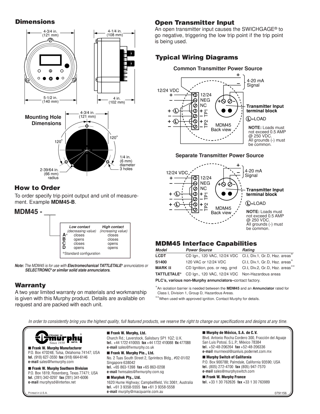
Dimensions |
|
(121 mm) | (108 mm) |
4 in. | |
(140 mm) | (102 mm) |
Mounting Hole |
|
|
| |
|
| (121 mm) | ||
Dimensions |
|
|
|
|
|
|
|
|
|
120 |
120 |
1/4 in. |
(6 mm) |
diameter |
3 holes |
Open Transmitter Input
An open transmitter input causes the SWICHGAGE® to go negative, triggering the low trip point if the trip point is being used.
Typical Wiring Diagrams
Common Transmitter Power Source
|
|
| |
|
|
| Signal |
12/24 VDC | 12/24 |
| |
|
| ||
| NEG |
|
|
| NC |
| Transmitter Input |
L | TP1 |
| terminal block |
|
| L =LOAD | |
L | TP2 |
| |
MDM45 |
| ||
| NOTE: Loads must | ||
|
| Back view | |
|
| not exceed 0.5 AMP | |
|
|
| |
@ 250 VDC.
All grounds
Separate Transmitter Power Source
(66 mm) |
radius |
How to Order
To order specify trip point output and unit of measure- ment. Example
MDM45 - ___
| Low contact | High contact |
(decreasing value) | (increasing value) | |
A* | closes | closes |
B | opens | closes |
12/24 VDC
L
L
12/24 | |
NEG |
|
NC |
|
TP1 |
|
TP2 | MDM45 |
| Back view |
Transmitter Input terminal block
L=LOAD
NOTE: Loads must not exceed 0.5 AMP @ 250 VDC.
All grounds
C | closes | opens |
D | opens | opens |
*Standard configuration
Note: The MDM45 is for use with Electromechanical TATTLETALE® annunciators or
SELECTRONIC® or similar solid state annunciators.
MDM45 Interface Capabilities
Model | Power Source | Rating | |
LCDT | CD Ign., 120 VAC, 12/24 VDC | Cl.I, Div.1, Gr. D, Haz. areas* |
|
S1400 | 120 VAC or 12/24 VDC | Cl.I, Div.1, Gr. D, Haz. areas* | |
MARK II | CD Ignition, pos. or neg. grnd | Cl.I, Div.2, Gr. D, Haz. areas** | |
TATTLETALE® | CD Ign., 120 VAC, 12/24 VDC | ||
PLC’s, various
Warranty
A two year limited warranty on materials and workmanship is given with this Murphy product. Details are available on request and are packed with each unit.
*An isolation barrier is needed between the MDM45 and an Annunciator rated for Class I, Division 1, Group D, Hazardous Areas.
**When used with approved ignition. Contact Murphy for details.
In order to consistently bring you the highest quality, full featured products, we reserve the right to change our specifications and designs at any time.
FRANK W. | ® |
Since 1939 | MFR. |
|
■Frank W. Murphy Manufacturer
P.O. Box 470248; Tulsa, Oklahoma 74147; USA tel. (918)
■Frank W. Murphy Southern Division
P.O. Box 1819; Rosenberg, Texas 77471; USA tel. (281)
Printed in U.S.A.
■Frank W. Murphy, Ltd.
Church Rd.; Laverstock, Salisbury SP1 1QZ; U.K.
tel. +44 1722 410055 fax +44 1722 410088 tlx 477088
■Frank W. Murphy Pte., Ltd.
No. 2 Tuas South Street 2, Sprintecs Bldg.,
tel. +65
■Murphek Pty., Ltd.
1620 Hume Highway; Campbellfield, Vic 3061; Australia tel. +61 3
■Murphy de México, S.A. de C.V.
Blvd. Antonio Rocha Cordero 300, Fracción del Aguaje San Luis Potosí, S.L.P.; México 78384
tel.
■Murphy Switch of California
P.O. Box 900788; Palmdale, California 93590; USA tel. (805)
■Frank W. Murphy France
tel. +33 1 30 762626 fax +33 1 30 763989
0791156