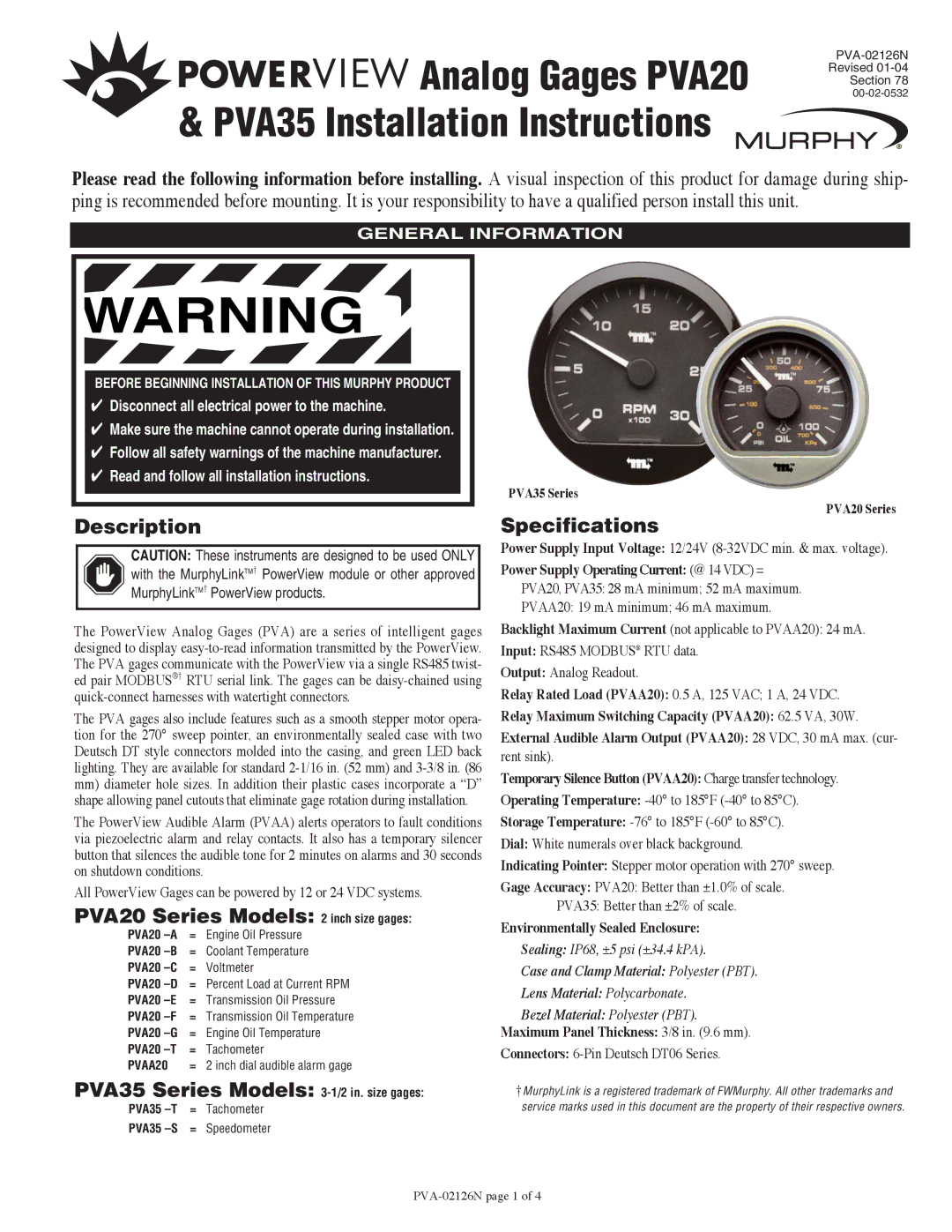


 Analog Gages PVA20 & PVA35 Installation Instructions
Revised
Section 78
Please read the following information before installing. A visual inspection of this product for damage during ship- ping is recommended before mounting. It is your responsibility to have a qualified person install this unit.
GENERAL INFORMATION
WARNING
BEFORE BEGINNING INSTALLATION OF THIS MURPHY PRODUCT
✔Disconnect all electrical power to the machine.
✔Make sure the machine cannot operate during installation.
✔Follow all safety warnings of the machine manufacturer.
✔Read and follow all installation instructions.
Description
CAUTION: These instruments are designed to be used ONLY with the MurphyLinkTM† PowerView module or other approved MurphyLinkTM† PowerView products.
The PowerView Analog Gages (PVA) are a series of intelligent gages designed to display
The PVA gages also include features such as a smooth stepper motor opera- tion for the 270° sweep pointer, an environmentally sealed case with two Deutsch DT style connectors molded into the casing, and green LED back lighting. They are available for standard
mm)diameter hole sizes. In addition their plastic cases incorporate a “D” shape allowing panel cutouts that eliminate gage rotation during installation.
The PowerView Audible Alarm (PVAA) alerts operators to fault conditions via piezoelectric alarm and relay contacts. It also has a temporary silencer button that silences the audible tone for 2 minutes on alarms and 30 seconds on shutdown conditions.
All PowerView Gages can be powered by 12 or 24 VDC systems.
PVA20 Series Models: 2 inch size gages:
PVA20 | = | Engine Oil Pressure |
PVA20 | = | Coolant Temperature |
PVA20 | = | Voltmeter |
PVA20 | = Percent Load at Current RPM | |
PVA20 | = | Transmission Oil Pressure |
PVA20 | = | Transmission Oil Temperature |
PVA20 | = | Engine Oil Temperature |
PVA20 | = | Tachometer |
PVAA20 | = 2 inch dial audible alarm gage | |
PVA35 Series Models:
PVA35
PVA35
PVA35 Series
PVA20 Series
Specifications
Power Supply Input Voltage: 12/24V
Power Supply Operating Current: (@ 14 VDC) = PVA20, PVA35: 28 mA minimum; 52 mA maximum. PVAA20: 19 mA minimum; 46 mA maximum.
Backlight Maximum Current (not applicable to PVAA20): 24 mA.
Input: RS485 MODBUS® RTU data.
Output: Analog Readout.
Relay Rated Load (PVAA20): 0.5 A, 125 VAC; 1 A, 24 VDC.
Relay Maximum Switching Capacity (PVAA20): 62.5 VA, 30W.
External Audible Alarm Output (PVAA20): 28 VDC, 30 mA max. (cur-
rent sink).
Temporary Silence Button (PVAA20): Charge transfer technology.
Operating Temperature:
Storage Temperature:
Dial: White numerals over black background.
Indicating Pointer: Stepper motor operation with 270° sweep.
Gage Accuracy: PVA20: Better than ±1.0% of scale. PVA35: Better than ±2% of scale.
Environmentally Sealed Enclosure:
Sealing: IP68, ±5 psi (±34.4 kPA).
Case and Clamp Material: Polyester (PBT).
Lens Material: Polycarbonate.
Bezel Material: Polyester (PBT).
Maximum Panel Thickness: 3/8 in. (9.6 mm).
Connectors: 6-Pin Deutsch DT06 Series.
†MurphyLink is a registered trademark of FWMurphy. All other trademarks and service marks used in this document are the property of their respective owners.
