Typical Connectors PIN Designation
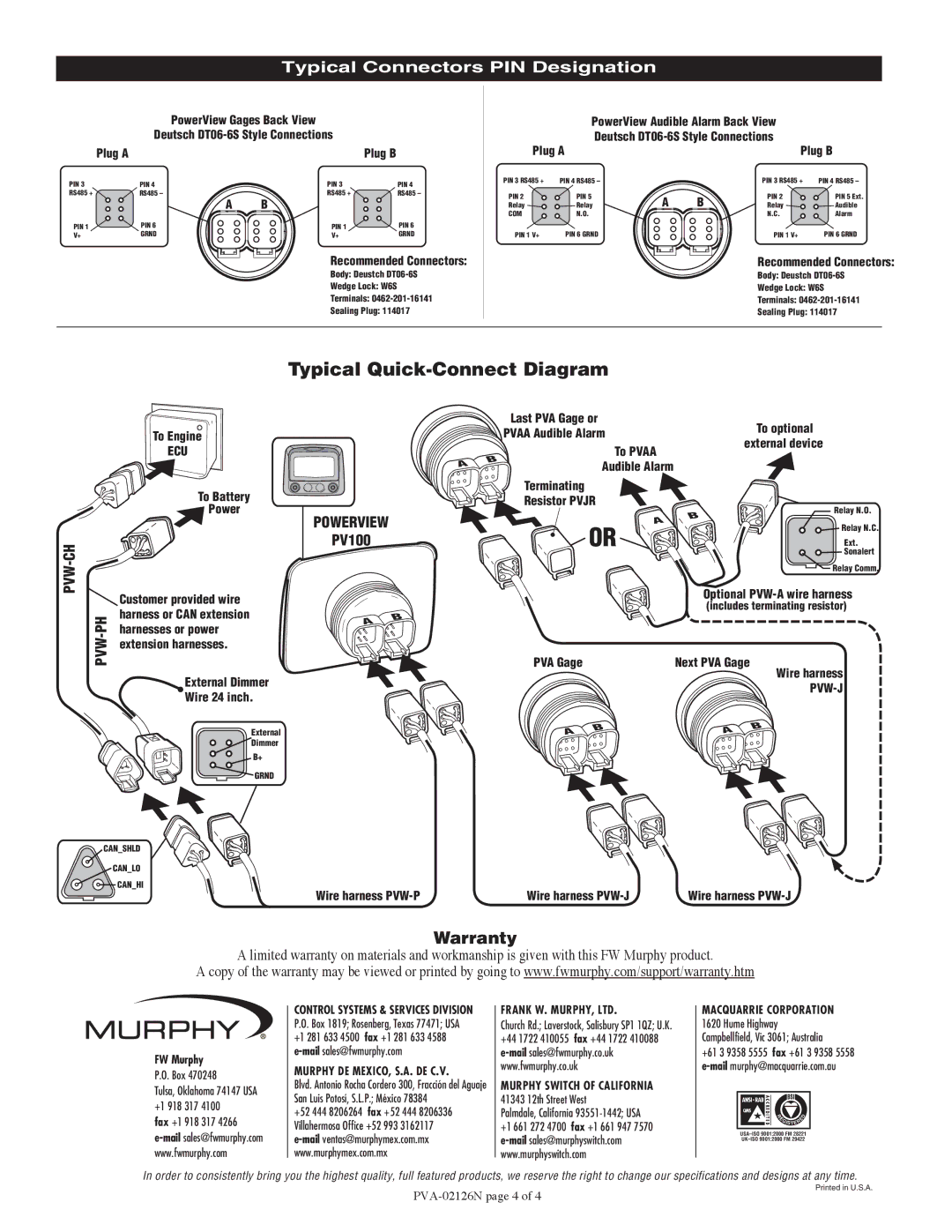
PowerView Gages Back View
Deutsch
| Plug A |
| Plug B |
PIN 3 | PIN 4 | PIN 3 | PIN 4 |
RS485 + | RS485 – | RS485 + | RS485 – |
| A | B |
|
PIN 1 | PIN 6 | PIN 1 | PIN 6 |
V+ | GRND | V+ | GRND |
Recommended Connectors:
Body: Deustch
Wedge Lock: W6S
Terminals:
Sealing Plug: 114017
| PowerView Audible Alarm Back View |
| |||
| Deutsch |
| |||
Plug A |
|
| Plug B | ||
PIN 3 RS485 + | PIN 4 RS485 – |
|
| PIN 3 RS485 + | PIN 4 RS485 – |
PIN 2 | PIN 5 | A | B | PIN 2 | PIN 5 Ext. |
Relay | Relay | Relay | Audible | ||
COM | N.O. |
|
| N.C. | Alarm |
PIN 1 V+ | PIN 6 GRND |
|
| PIN 1 V+ | PIN 6 GRND |
Recommended Connectors:
Body: Deustch
Wedge Lock: W6S
Terminals:
Sealing Plug: 114017
Typical Quick-Connect Diagram
PVW-CH
To Engine
ECU
To Battery
![]() Power
Power
| Customer provided wire | |
PH | harness or CAN extension | |
harnesses or power | ||
PVW- | ||
extension harnesses. | ||
| ||
| External Dimmer | |
| Wire 24 inch. | |
| External | |
| Dimmer | |
| B+ | |
| GRND |
Last PVA Gage or
|
|
| PVAA Audible Alarm |
| To optional | |
|
|
|
| external device | ||
|
|
|
| To PVAA |
| |
|
| B |
|
|
| |
| A |
| Audible Alarm |
|
| |
|
|
|
|
| ||
|
|
|
|
|
| |
|
|
| Terminating |
|
|
|
|
|
| Resistor PVJR |
| Relay N.O. | |
POWERVIEW |
|
|
|
| B | |
|
|
| A | Relay N.C. | ||
|
|
|
| |||
PV100 |
|
|
| OR |
| Ext. |
|
|
|
|
|
| Sonalert |
|
|
|
|
|
| Relay Comm. |
|
|
|
|
| Optional | |
|
|
|
|
| (includes terminating resistor) | |
A | B |
|
|
|
|
|
|
|
|
|
|
| |
|
|
| PVA Gage |
| Next PVA Gage | |
|
|
|
|
|
| Wire harness |
|
|
|
|
|
|
|
|
|
| A | B | A | B |
|
|
|
| |||
|
|
|
|
| ||
Wire harness | Wire harness | Wire harness |
Warranty
A limited warranty on materials and workmanship is given with this FW Murphy product.
A copy of the warranty may be viewed or printed by going to www.fwmurphy.com/support/warranty.htm
FW Murphy
P.O. Box 470248
Tulsa, Oklahoma 74147 USA +1 918 317 4100
fax +1 918 317 4266
CONTROL SYSTEMS & SERVICES DIVISION P.O. Box 1819; Rosenberg, Texas 77471; USA +1 281 633 4500 fax +1 281 633 4588
MURPHY DE MEXICO, S.A. DE C.V.
Blvd. Antonio Rocha Cordero 300, Fracción del Aguaje San Luis Potosí, S.L.P.; México 78384
+52 444 8206264 fax +52 444 8206336 Villahermosa Office +52 993 3162117
FRANK W. MURPHY, LTD.
Church Rd.; Laverstock, Salisbury SP1 1QZ; U.K. +44 1722 410055 fax +44 1722 410088
MURPHY SWITCH OF CALIFORNIA
41343 12th Street West
Palmdale, California 93551-1442; USA
+1 661 272 4700 fax +1 661 947 7570
MACQUARRIE CORPORATION 1620 Hume Highway Campbellfield, Vic 3061; Australia
+61 3 9358 5555 fax +61 3 9358 5558
| E |
|
| D |
|
|
| ||
| R |
|
|
|
|
|
| E |
|
| GISTER |
| ||
|
|
|
|
|
In order to consistently bring you the highest quality, full featured products, we reserve the right to change our specifications and designs at any time.
Printed in U.S.A.