PVA20, PVA35 and PVAA SERIES Typical Wirings For 12 and 24 VDC
WARNING: Disconnect battery negative cable before wiring or service. Devices containing solid state components can be damaged or caused to malfunction when used in systems which incorporate inductive loads (e.g. relays, solenoids, etc.) that can generate voltage spikes. To reduce the potential for this type of damage, install a fly back or clamping diode across all inductive loads. Use Murphy diode package
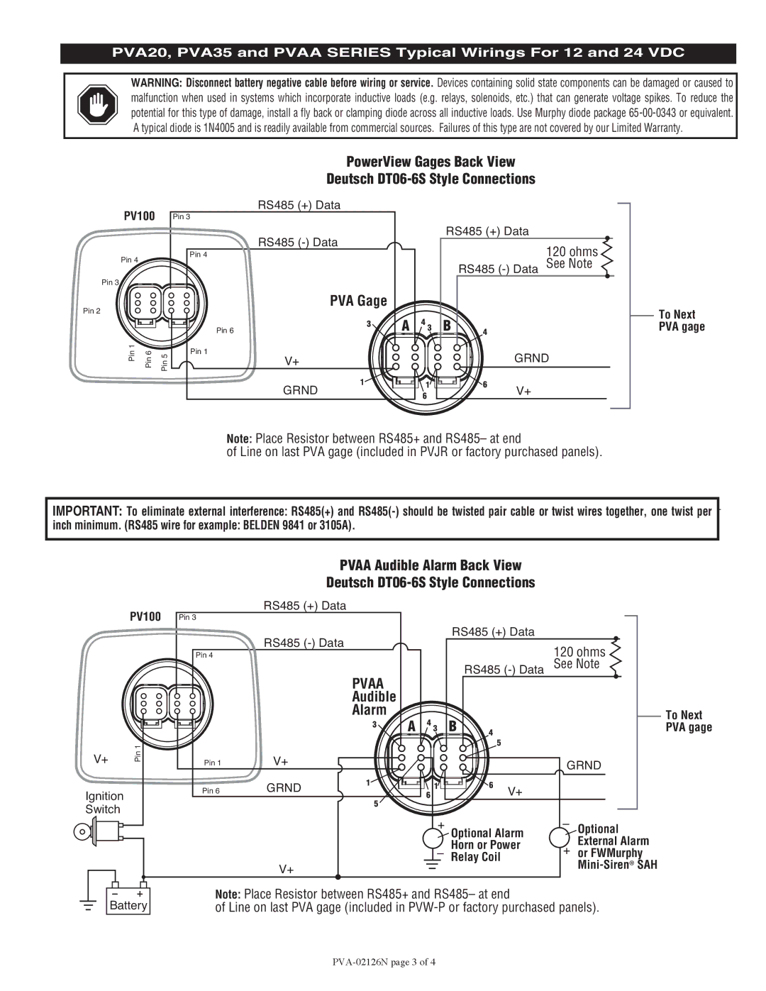
PowerView Gages Back View
Deutsch DT06-6S Style Connections
PV100
Pin 4
Pin 3
Pin 2
Pin 1 | Pin 6 | Pin 5 |
RS485 (+) Data
Pin 3
RS485
Pin 4
PVA Gage
3 | A | 4 |
Pin 6 | 3 |
Pin 1
V+
11
GRND6
RS485 (+) Data
120 ohms RS485
B | 4 |
GRND
6 | V+ |
|
To Next PVA gage
Note: Place Resistor between RS485+ and RS485– at end
of Line on last PVA gage (included in PVJR or factory purchased panels).
IMPORTANT: To eliminate external interference: RS485(+) and
inch minimum. (RS485 wire for example: BELDEN 9841 or 3105A).
PV100
V+ | Pin 1 |
|
Ignition
Switch
Battery
|
| PVAA Audible Alarm Back View |
|
| |||||
|
| Deutsch |
|
| |||||
| RS485 (+) Data |
|
|
|
|
|
|
| |
Pin 3 |
|
|
|
|
|
|
|
|
|
| RS485 |
|
| RS485 (+) Data |
|
| |||
|
|
|
|
|
| 120 ohms | |||
Pin 4 |
|
|
|
|
|
|
| ||
|
| PVAA |
|
|
| RS485 | See Note | ||
|
|
|
|
|
|
|
|
| |
|
| Audible |
|
|
|
|
|
|
|
|
| Alarm | A | 4 | B |
|
|
| To Next |
|
| 3 | 4 |
|
| PVA gage | |||
|
|
| 3 |
|
| ||||
|
|
|
|
|
| 5 |
|
|
|
Pin 1 | V+ |
|
|
|
|
|
| GRND | |
|
|
|
|
|
|
|
| ||
Pin 6 | GRND | 1 |
| 1 |
| 6 | V+ |
|
|
|
|
|
|
| |||||
|
| 5 |
| 6 |
|
|
|
| |
|
|
|
|
|
|
|
|
| |
|
|
|
| + | Optional Alarm | – | Optional | ||
|
|
|
|
|
| External Alarm | |||
|
|
|
|
| Horn or Power | + | |||
|
|
|
| – | or FWMurphy | ||||
| V+ |
|
|
| Relay Coil |
|
| ||
|
|
|
|
|
|
|
| ||
|
|
|
|
|
|
|
|
| |
Note: Place Resistor between RS485+ and RS485– at end
of Line on last PVA gage (included in