FRANK W. | ® | |
| ||
|
| Revised |
MFR. |
| Catalog Section 50 |
|
|
|
SELECTRONIC® Annunciator
Series 1400
■ 32 N.O. or N.C. Sensors for Alarm or Shutdown
■ Alphanumeric Display ■ Start/Run Timer
■ Pre/Post Lube Timer
■ Four Control Relay Outputs ■ Field Adjustable
■ EPROM Memory
®
Approved for Class I, Division 1, Group D
Description
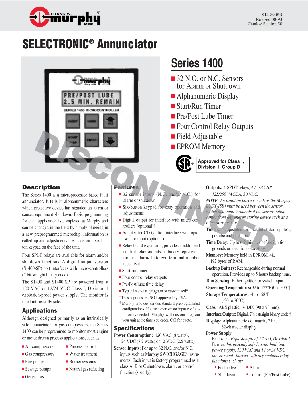
The Series 1400 is a microprocessor based fault annunciator. It tells in alphanumeric characters which protective device has signaled an alarm or caused equipment shutdown. Basic programming for each application is completed at Murphy and can be changed in the field by simply plugging in a new preprogrammed microchip. Information is called up and adjustments are made on a
Four SPDT relays are available for alarm and/or shutdown functions. A digital output version
The S1400 and
Applications
Although designed primarily as an intrinsically safe annunciator for gas compressors, the Series 1400 can be programmed to monitor most engine or motor driven process applications, such as:
■ Air compressors | ■ Process control |
■ Gas compressors | ■ Water treatment |
■ Fire pumps | ■ Burner systems |
■ Sewage pumps | ■ Natural gas refueling |
■ Generators |
|
Features
■32 sensor inputs (N.O. and/or N.C.) for alarm or shutdown
■
■Digital output for interface with
■Adapter for CD ignition interface with opto- isolator input (optional)†
■Relay board expansion, provides 7 additional control relay outputs or binary representa- tion of alarm/shutdown terminal number (specify)†
■
■Four control relay outputs
■Pre/Post lube time delay
■Typical standard program or customized*
†These options are NOT approved by CSA.
*Murphy provides various standard preprogrammed configurations. If a customer sensor input configu- ration is needed, Murphy will custom program your unit at the time you order. Call for quote.
Specifications
Power Consumption: 120 VAC (8 watts), 24 VDC (7.2 watts) or 12 VDC (2.5 watts).
Sensor Inputs: For up to 32 N.O. and/or N.C. inputs such as Murphy SWICHGAGE® instru- ments. Each input is factory programmed as a class A, B or C shutdown, alarm, or control function (specify).
Outputs:
NOTE: An isolation barrier (such as the Murphy
Timers: 4 adjustable for: lockout at
Time Delay: Up to 0.9 minutes before ignition grounds or electric motor stops.
Memory: Memory held in EPROM, 4k, 192 bytes of RAM.
Backup Battery: Rechargeable during normal operation. Provides up to 5 hours backup time.
Run Sensing: Either ignition or switch input.
Operating Temperatures: 32 to 122°F (0 to 50°C).
Storage Temperatures:
Case: ABS plastic, 1/4 DIN (90 x 90 mm).
Interface Output: Digital, 7 bit straight binary code.†
Display: Alphanumeric dot matrix, 2 line
Power Supply
Enclosure:
Barrier: Intrinsically safe barrier built into power supply, 120 VAC and 12 or 24 VDC power supply barrier with dry contacts relay functions such as:
• Fuel valve | • Alarm |
• Shutdown | • Control (Pre/Post Lube). |
