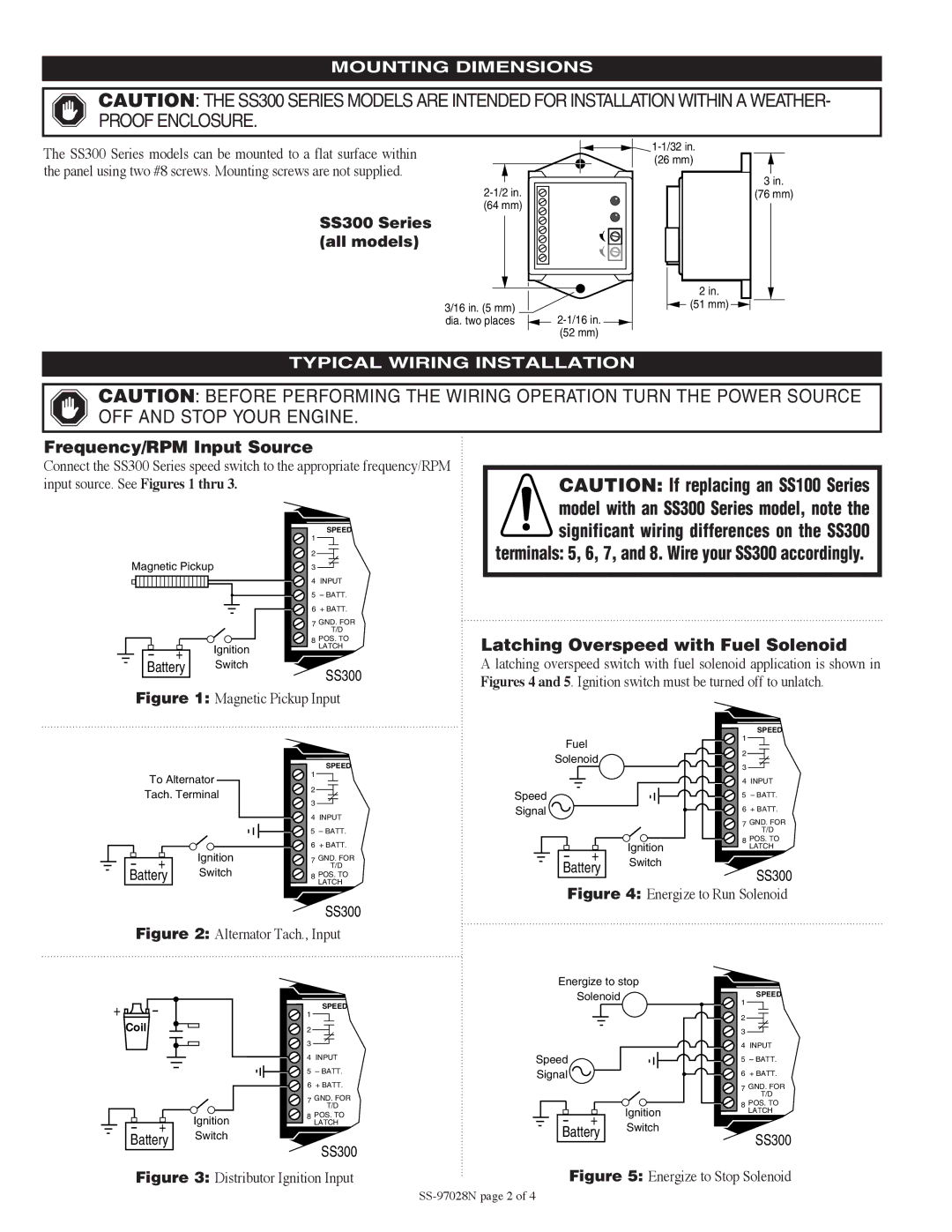
SS300 Series specifications
The Murphy SS300 Series represents a significant advancement in the realm of engine monitoring and control solutions. Recognized for its precision and reliability, the SS300 Series is designed primarily for diesel and natural gas engines, making it a staple in various applications, including industrial machinery, marine vessels, and power generation systems.One of the standout features of the Murphy SS300 Series is its robust monitoring capabilities. The system is equipped with advanced sensors and gauges that allow for real-time data collection on important engine parameters such as oil pressure, coolant temperature, fuel levels, and RPM. This data is crucial for ensuring optimal engine performance and longevity, as it enables operators to identify potential issues before they escalate into costly failures.
The SS300 Series also incorporates state-of-the-art communication technologies. With support for protocols like CANbus, Modbus, and Serial communications, the system can be easily integrated into existing setups, allowing for seamless data exchange between the engine control unit and other important components. This feature not only enhances operational efficiency but also simplifies the overall management of the engine and its auxiliary systems.
Another key characteristic of the SS300 Series is its user-friendly interface. Featuring a high-resolution display, the system presents critical information in an easily digestible format. Users can access menu-driven functions with simple navigation, enabling them to monitor engine performance and make adjustments on-the-fly, even in challenging environments.
Durability is a core design principle of the SS300 Series. Built to withstand harsh conditions, the system is housed in rugged enclosures that offer protection against moisture, vibration, and extreme temperatures. This ensures dependable performance in demanding applications, whether onboard a ship or in a remote power plant.
Additionally, the Murphy SS300 Series offers customizable alarm settings and fault diagnostics. Operators can set thresholds for various parameters and receive immediate alerts if any readings exceed these levels. This proactive approach to engine management not only enhances safety but also minimizes downtime, allowing businesses to maintain productivity.
In conclusion, the Murphy SS300 Series stands out as a leading engine monitoring and control solution through its advanced features, robust communication technologies, user-friendly design, and durability. It offers a comprehensive toolset for operators aiming to optimize engine performance while ensuring safety and reliability across diverse applications.

