TYPICAL WIRING INSTALLATION (continued)

Non Latching Overspeed Switch with Air Shutoff Solenoid

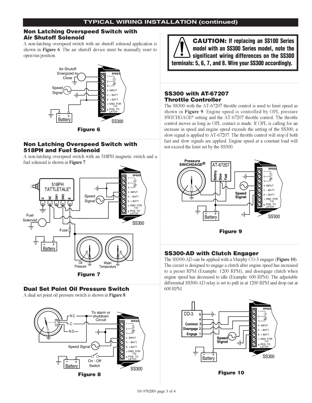
A non-latching overspeed switch with air shutoff solenoid application is shown in Figure 6. The air shutoff device must be manually reset to open/run position.

CAUTION: If replacing an SS100 Series model with an SS300 Series model, note the significant wiring differences on the SS300

terminals: 5, 6, 7, and 8. Wire your SS300 accordingly.

Air Shutoff

Energized to

Close

Speed

Signal

-- + Battery

Figure 6

SPEED

1

2

3

4 INPUT

5 – BATT.

6 + BATT.

7 GND. FOR

T/D

8 POS. TO

LATCH

SS300

SS300 with AT-67207

Throttle Controller

The SS300 with the AT-67207 throttle control is used to limit speed as shown in Figure 9. Engine speed is controlled by OPL pressure SWICHGAGE® setting and the AT-67207 throttle control. The throttle control moves as long as OPL contact is made. If OPL is calling for an increase in speed and engine speed exceeds the setting of the SS300, a slow signal is applied to AT-67207. The throttle control will stop if both fast and slow signals are applied. Engine speed at a constant load will

Non Latching Overspeed Switch with 518PH and Fuel Solenoid

not exceed the limit set by the SS300.

A non-latching overspeed switch with an 518PH magnetic switch and a fuel solenoid is shown in Figure 7.

Pressure

SWICHGAGE®

AT-67207

SPEED

1

518PH

TATTLETALE®

G

NC

SW1

SW2

B


Speed


Signal

SPEED

1

2

3

4 INPUT

5 – BATT.

6 + BATT.

7 GND. FOR

T/D

Speed Signal

2

3

4 INPUT

5 – BATT.

6 + BATT.

7 GND. FOR

T/D

8 POS. TO

LATCH

Fuel

Solenoid

8 POS. TO

LATCH

SS300

--+

Battery

SS300

Fuse

--+

Battery

OilWater

Pressure Temperature

Figure 7

Figure 9

SS300-AD with Clutch Engager

The SS300-AD can be applied with a Murphy CO-3 engager (Figure 10). The circuit is designed to engage a clutch after engine speed has increased to a preset RPM (Example: 1200 RPM), and disengage clutch when engine speed has decreased to idle (Example: 600 RPM). The adjustable differential SS300-AD relay is set to pull in at 1200 RPM and drop out at

Dual Set Point Oil Pressure Switch

A dual set point oil pressure switch is shown in Figure 8.

600 RPM.

To alarm or

N.C. shutdown

Circuit

C

N.O.

Speed Signal

--+ On - Off

Battery

Switch

Figure 8

SPEED

1

2

3

4 INPUT

5 – BATT.

6 + BATT.

7 GND. FOR

T/D

8 POS. TO

LATCH

SS300

CO-3 5

4 Common 3 Disengage 2

Engage 1

Speed

Signal

-- + Battery

Figure 10

SPEED

1

2

3

4 INPUT

5 – BATT.

6 + BATT.

7 GND. FOR

T/D

8 POS. TO

LATCH

SS300

SS-97028N page 3 of 4

Page 3
Image 3
Murphy SS300 Series Non Latching Overspeed Switch with Air Shutoff Solenoid, SS300 with AT-67207 Throttle Controller

SS300 Series specifications

The Murphy SS300 Series represents a significant advancement in the realm of engine monitoring and control solutions. Recognized for its precision and reliability, the SS300 Series is designed primarily for diesel and natural gas engines, making it a staple in various applications, including industrial machinery, marine vessels, and power generation systems.

One of the standout features of the Murphy SS300 Series is its robust monitoring capabilities. The system is equipped with advanced sensors and gauges that allow for real-time data collection on important engine parameters such as oil pressure, coolant temperature, fuel levels, and RPM. This data is crucial for ensuring optimal engine performance and longevity, as it enables operators to identify potential issues before they escalate into costly failures.

The SS300 Series also incorporates state-of-the-art communication technologies. With support for protocols like CANbus, Modbus, and Serial communications, the system can be easily integrated into existing setups, allowing for seamless data exchange between the engine control unit and other important components. This feature not only enhances operational efficiency but also simplifies the overall management of the engine and its auxiliary systems.

Another key characteristic of the SS300 Series is its user-friendly interface. Featuring a high-resolution display, the system presents critical information in an easily digestible format. Users can access menu-driven functions with simple navigation, enabling them to monitor engine performance and make adjustments on-the-fly, even in challenging environments.

Durability is a core design principle of the SS300 Series. Built to withstand harsh conditions, the system is housed in rugged enclosures that offer protection against moisture, vibration, and extreme temperatures. This ensures dependable performance in demanding applications, whether onboard a ship or in a remote power plant.

Additionally, the Murphy SS300 Series offers customizable alarm settings and fault diagnostics. Operators can set thresholds for various parameters and receive immediate alerts if any readings exceed these levels. This proactive approach to engine management not only enhances safety but also minimizes downtime, allowing businesses to maintain productivity.

In conclusion, the Murphy SS300 Series stands out as a leading engine monitoring and control solution through its advanced features, robust communication technologies, user-friendly design, and durability. It offers a comprehensive toolset for operators aiming to optimize engine performance while ensuring safety and reliability across diverse applications.