Typical Wiring Tech Sheet for Magnetic Switches and TATTLETALE® Annunciators
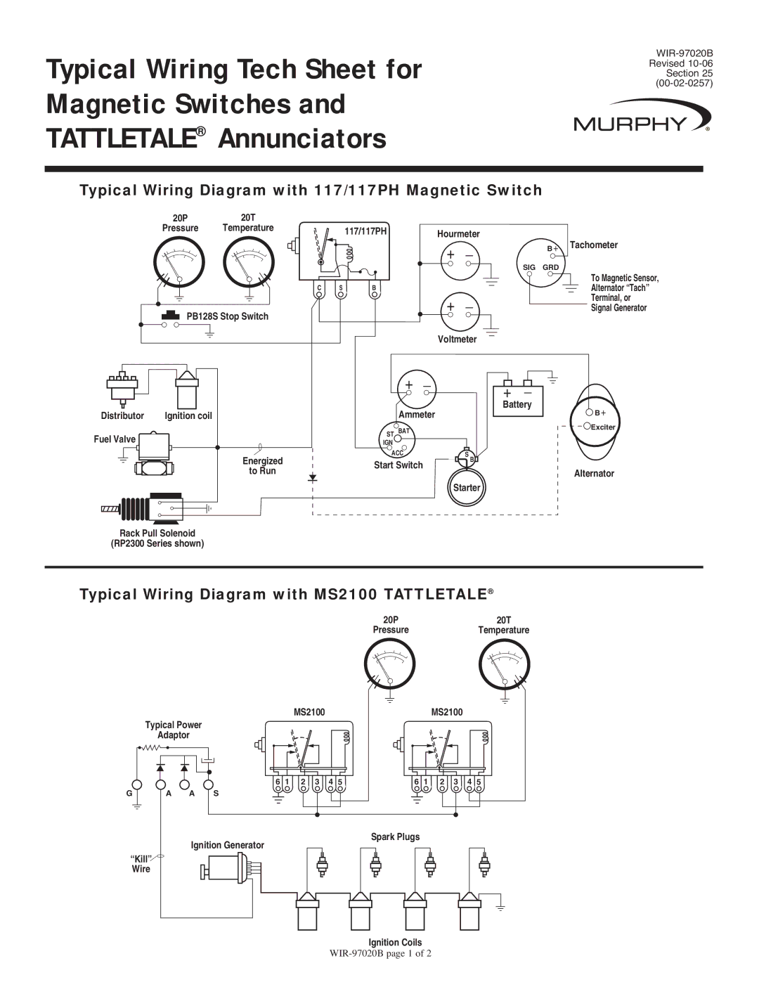
Typical Wiring Diagram with 117/117PH Magnetic Switch
20P | 20T |
|
|
|
|
|
Pressure | Temperature | 117/117PH | Hourmeter |
|
| |
|
|
| Tachometer | |||
|
|
| + | _ | B + | |
|
|
|
|
|
| |
C S
PB128S Stop Switch
Distributor | Ignition coil |
Fuel Valve
Energized
to Run
| SIG | GRD |
|
| To Magnetic Sensor, |
B |
| Alternator “Tach” |
+ | _ | Terminal, or |
Signal Generator | ||
Voltmeter |
| |
+ _ | + _ |
|
Ammeter | Battery | B + |
| ||
ST BAT |
| Exciter |
|
| |
IGN |
|
|
ACC | S |
|
Start Switch | B |
|
| Alternator | |
|
| |
Starter |
| |
Rack Pull Solenoid
(RP2300 Series shown)
Typical Wiring Diagram with MS2100 TATTLETALE®
20P | 20T |
Pressure | Temperature |
MS2100MS2100
Typical Power
Adaptor
6 1 | 2 | 3 | 4 5 | 6 1 | 2 | 3 | 4 5 |
G |
|
| A A S |
|
|
|
|
Spark Plugs
Ignition Generator
“Kill”![]()
Wire
Ignition Coils