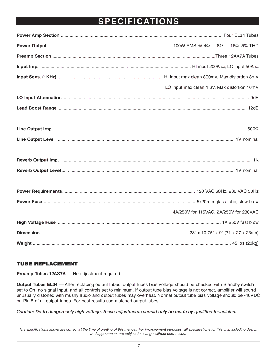
GTH-100 specifications
The Nady Systems GTH-100 is a state-of-the-art wireless guitar system that has gained popularity among musicians for its impressive performance and reliability. Designed specifically for guitarists, the GTH-100 combines cutting-edge technology with user-friendly features to deliver exceptional sound quality and versatility on stage or in the studio.One of the main features of the GTH-100 is its UHF (Ultra High Frequency) transmission system, which allows for a high-quality audio signal with minimal interference. Operating in the 900 MHz frequency range, the GTH-100 provides a generous range of up to 100 feet, enabling players to move freely while performing without the restrictions of a cable. This technology ensures clear, consistent sound reproduction, even in crowded environments where other wireless systems might struggle.
Another key characteristic of the GTH-100 is its ease of use. The system includes a plug-and-play design, making setup and tear-down quick and straightforward. Musicians can simply plug the transmitter into their guitar and connect the receiver to their amplifier or pedalboard, and they are ready to rock. Additionally, the GTH-100 features an auto-scan function that automatically selects the best available channel, minimizing setup time while maximizing reliability during performances.
The transmitter's design is both compact and lightweight, providing comfort and convenience for guitarists. Powered by a rechargeable lithium-ion battery, the GTH-100 offers an impressive battery life of up to 8 hours, ensuring that musicians can perform lengthy sets without worrying about running out of power. The built-in battery indicator allows players to monitor their power levels easily, providing peace of mind.
In terms of sound quality, the GTH-100 boasts a wide frequency response that captures the nuances of a guitar's tone, from crisp highs to deep lows. The system also features advanced audio compression technologies that preserve dynamics and clarity under varying conditions, ensuring that musicians can deliver their sound accurately without sacrificing quality.
Overall, the Nady Systems GTH-100 is an innovative wireless solution for guitarists looking to enhance their performance experience. With its reliable UHF transmission, user-friendly design, extended battery life, and superb audio quality, the GTH-100 truly stands out in the competitive market of wireless guitar systems, making it an excellent choice for performers of all levels.
