FRONT CONTROLS AND CONNECTIONS
| CHANNEL SECTION | |
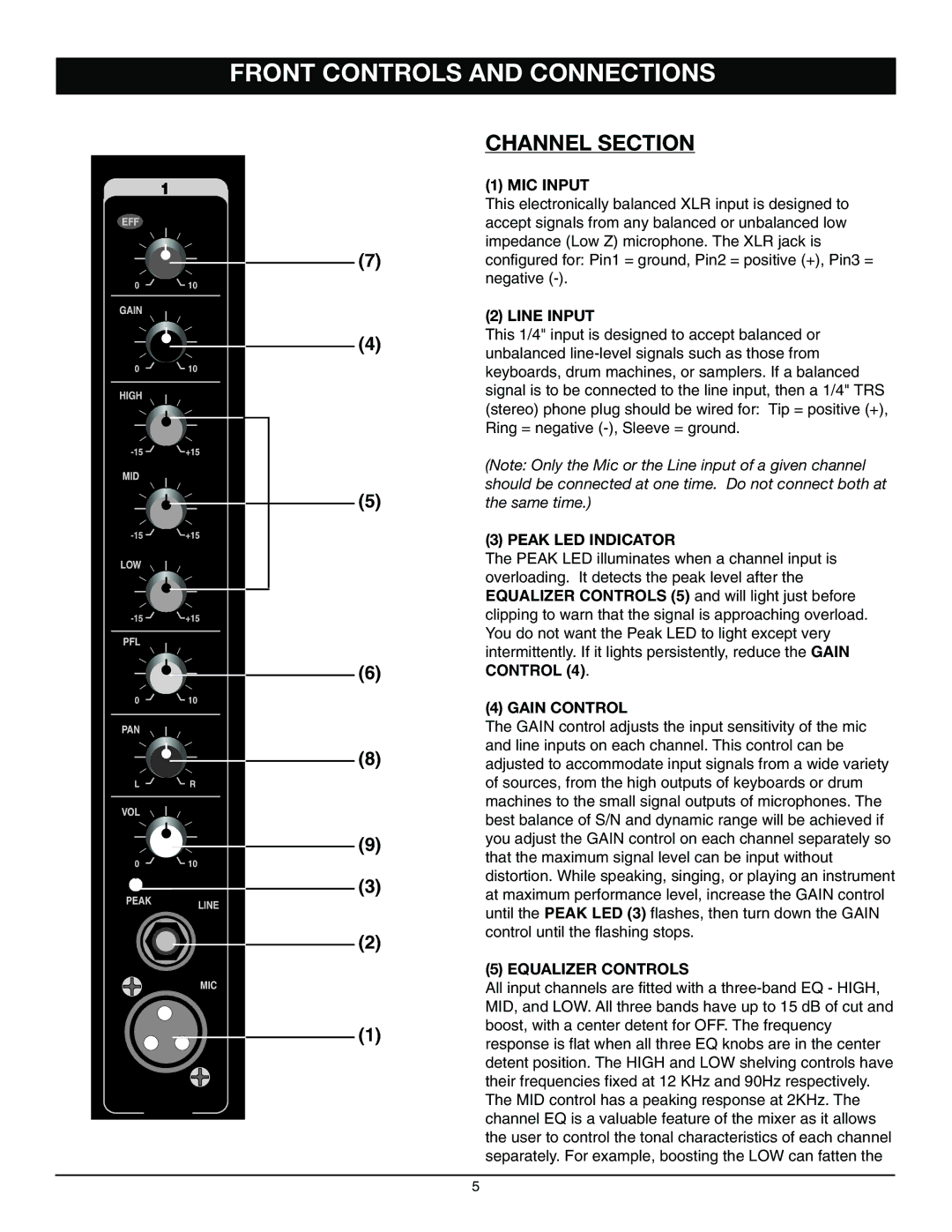
| (1) MIC INPUT | |
| This electronically balanced XLR input is designed to | |
| accept signals from any balanced or unbalanced low | |
(7) | impedance (Low Z) microphone. The XLR jack is | |
configured for: Pin1 = ground, Pin2 = positive (+), Pin3 = | ||
| negative | |
| (2) LINE INPUT | |
(4) | This 1/4" input is designed to accept balanced or | |
unbalanced | ||
| ||
| keyboards, drum machines, or samplers. If a balanced | |
| signal is to be connected to the line input, then a 1/4" TRS | |
| (stereo) phone plug should be wired for: Tip = positive (+), | |
| Ring = negative | |
| (Note: Only the Mic or the Line input of a given channel | |
(5) | should be connected at one time. Do not connect both at | |
the same time.) | ||
| (3) PEAK LED INDICATOR | |
| The PEAK LED illuminates when a channel input is | |
| overloading. It detects the peak level after the | |
| EQUALIZER CONTROLS (5) and will light just before | |
| clipping to warn that the signal is approaching overload. | |
| You do not want the Peak LED to light except very | |
| intermittently. If it lights persistently, reduce the GAIN | |
(6) | CONTROL (4). | |
| (4) GAIN CONTROL | |
| The GAIN control adjusts the input sensitivity of the mic | |
(8) | and line inputs on each channel. This control can be | |
adjusted to accommodate input signals from a wide variety | ||
| of sources, from the high outputs of keyboards or drum | |
| machines to the small signal outputs of microphones. The | |
| best balance of S/N and dynamic range will be achieved if | |
(9) | you adjust the GAIN control on each channel separately so | |
| that the maximum signal level can be input without |
(3) | distortion. While speaking, singing, or playing an instrument | |
at maximum performance level, increase the GAIN control | ||
| ||
| until the PEAK LED (3) flashes, then turn down the GAIN | |
(2) | control until the flashing stops. | |
| ||
| (5) EQUALIZER CONTROLS | |
| All input channels are fitted with a | |
| MID, and LOW. All three bands have up to 15 dB of cut and | |
(1) | boost, with a center detent for OFF. The frequency | |
response is flat when all three EQ knobs are in the center | ||
| ||
| detent position. The HIGH and LOW shelving controls have | |
| their frequencies fixed at 12 KHz and 90Hz respectively. | |
| The MID control has a peaking response at 2KHz. The | |
| channel EQ is a valuable feature of the mixer as it allows | |
| the user to control the tonal characteristics of each channel | |
| separately. For example, boosting the LOW can fatten the |
5
