9
BLOWER INSTALLATION
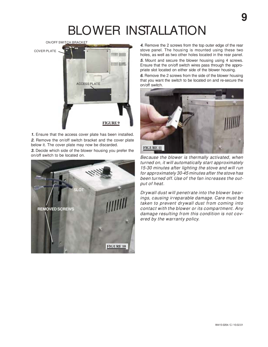
ON/OFF SWITCH BRACKET
COVER PLATE
ACCESS PLATE
FIGURE 9
1.Ensure that the access cover plate has been installed.
2.Remove the on/off switch bracket and the cover plate below it. The cover plate may now be discarded.
3.Decide which side of the blower housing you prefer the on/off switch to be located on.
SLOT
REMOVED SCREWS
4.Remove the 2 screws from the top outer edge of the rear stove panel. The housing is mounted using these two holes, as well as two other holes located in the rear panel.
5.Mount and secure the blower housing using 4 screws. Ensure that the on/off switch wires pass through the appro- priate slot located on either side of the blower housing.
6.Remove the 2 screws from the side of the blower housing that you want the switch to be located on and
FIGURE 11
Because the blower is thermally activated, when turned on, it will automatically start approximately
Drywall dust will penetrate into the blower bear- ings, causing irreparable damage. Care must be taken to prevent drywall dust from coming into contact with the blower or its compartment. Any damage resulting from this condition is not cov- ered by the warranty policy.
FIGURE 10