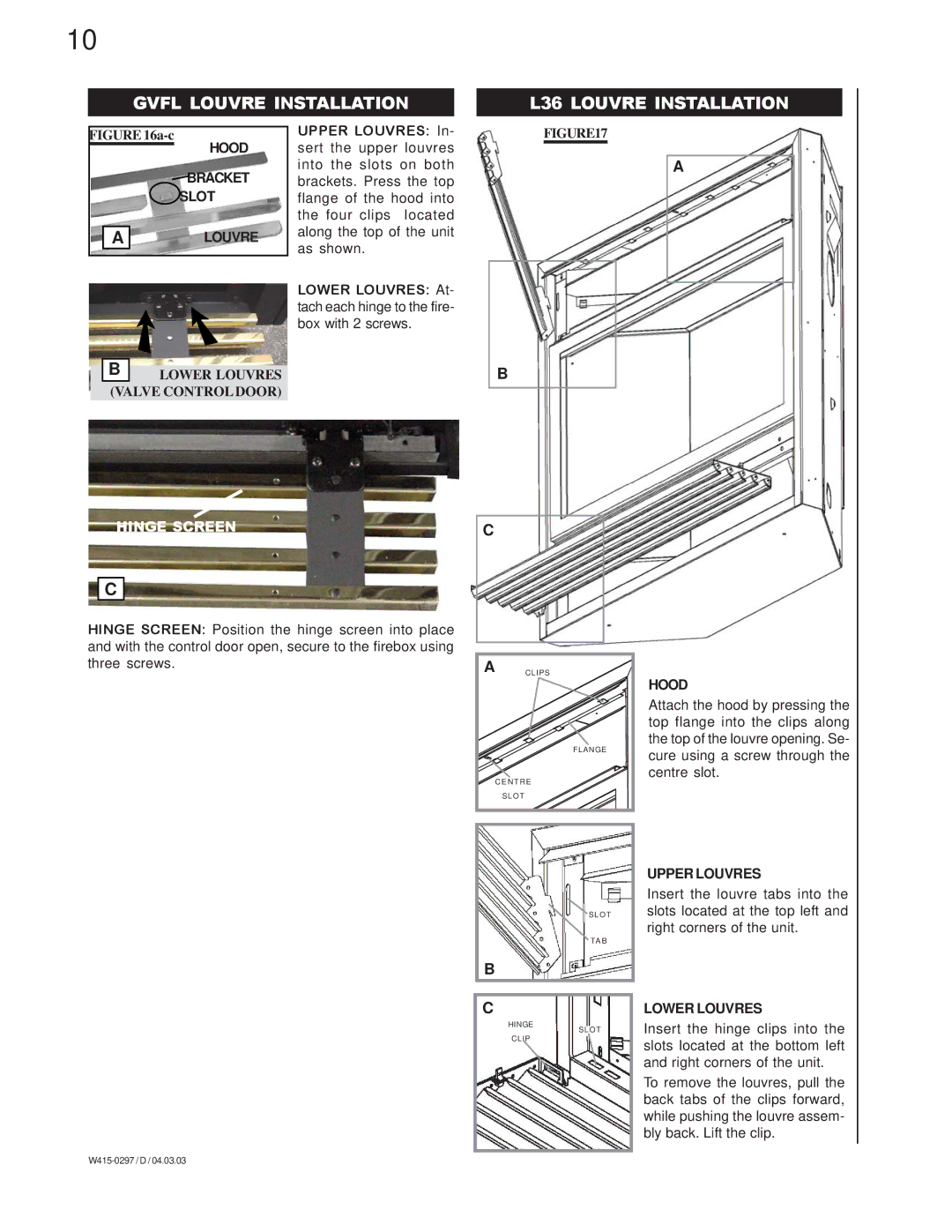
GVF36P, GVF36N specifications
Napoleon Grills has long been synonymous with quality outdoor cooking, and the GVF36P and GVF36N models are no exception. Both grills offer exceptional performance and innovative features, making them ideal for serious barbecue enthusiasts and casual grillers alike.The GVF36P and GVF36N are part of the Napoleon Prestige lineup, showcasing superior craftsmanship and design. These models are equipped with a powerful multi-burner system that delivers intense heat, allowing chefs to sear steaks and deliver restaurant-quality results in the comfort of their backyard. The highly efficient stainless steel burners ensure even heat distribution, minimizing hot spots and delivering consistent cooking temperatures.
One of the standout features of these grills is the iconic Napoleon infrared rear burner. This unique technology allows for perfect rotisserie cooking, enabling users to achieve beautifully cooked, juicy meats while sealing in flavors. Both models come with an included rotisserie kit, making it easy to elevate your outdoor cooking experience.
The GVF36P is specifically designed for propane fuel, while the GVF36N operates on natural gas, catering to a wide range of users and preferences. The dual fuel options make it highly versatile, allowing homeowners to choose the best fit for their outdoor setup.
In terms of construction, both models feature a robust, powder-coated steel frame and stainless steel components, ensuring durability and resistance to the elements. The cooking surfaces consist of cast iron grates that not only retain heat well but also provide ideal sear marks, enhancing the visual presentation of grilled foods.
Additional features include integrated LED lights in the control knobs, enhancing visibility during nighttime grilling, and a convenient side shelf for food preparation. The grills also come equipped with a built-in temperature gauge, allowing chefs to monitor their cooking without lifting the lid.
With a focus on ease of use, the GVF36P and GVF36N incorporate an electronic ignition system for reliable, quick starting, so you can get cooking without delay. The spacious cooking area provides ample room for preparing multiple dishes simultaneously, making it perfect for gatherings and entertaining.
In summary, the Napoleon Grills GVF36P and GVF36N are sophisticated grilling solutions that blend performance, technology, and durability. With their versatile fuel options, innovative features, and high-quality construction, these grills are designed to meet the needs of any grilling enthusiast, offering the perfect platform for unforgettable outdoor cooking experiences.

