Manuals
/
National
/
TV and Video
/
TV Converter Box
National
ADC12V170
manual
Layer 2 Ground
Models:
ADC12V170
1
10
15
15
Download
15 pages
51.53 Kb
7
8
9
10
11
12
13
14
Evaluation Board Schematic
Layer 4 Signal
PD Jumper Mode Setting
Power requirements
Page 10
Image 10
ADC12V170 Evaluation Board User’s Guide
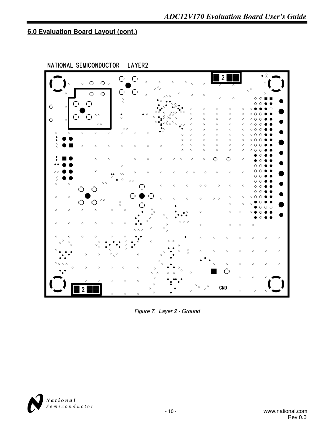
6.0 Evaluation Board Layout (cont.)
Figure 7. Layer 2 - Ground
N
- 10 -
www.national.com
Rev 0.0
Page 9
Page 11
Page 10
Image 10
Page 9
Page 11
Contents
Page
ADC12V170 Evaluation Board User’s Guide
Jumper
Evaluation Board Jumper Positions
PD Jumper Mode Setting
Jumper Setting Clock Mode
Output Data Format
Clock Input
Connecting Power and Signal Sources
Analog Input
ADC Reference and Input Common Mode
Board Outputs
Power requirements
Evaluation Board Schematic
Schematic
Evaluation Board Layout
Layer 2 Ground
Layer 3 Power
Layer 4 Signal
ADC12V170HFEB For Fin 150 MHz
ADC
ADC12V170LFEB For Fin 150 MHz
Life Support Policy
Top
Page
Image
Contents