54LS14/DM74LS14 Hex Inverters with Schmitt Trigger Inputs
General Description
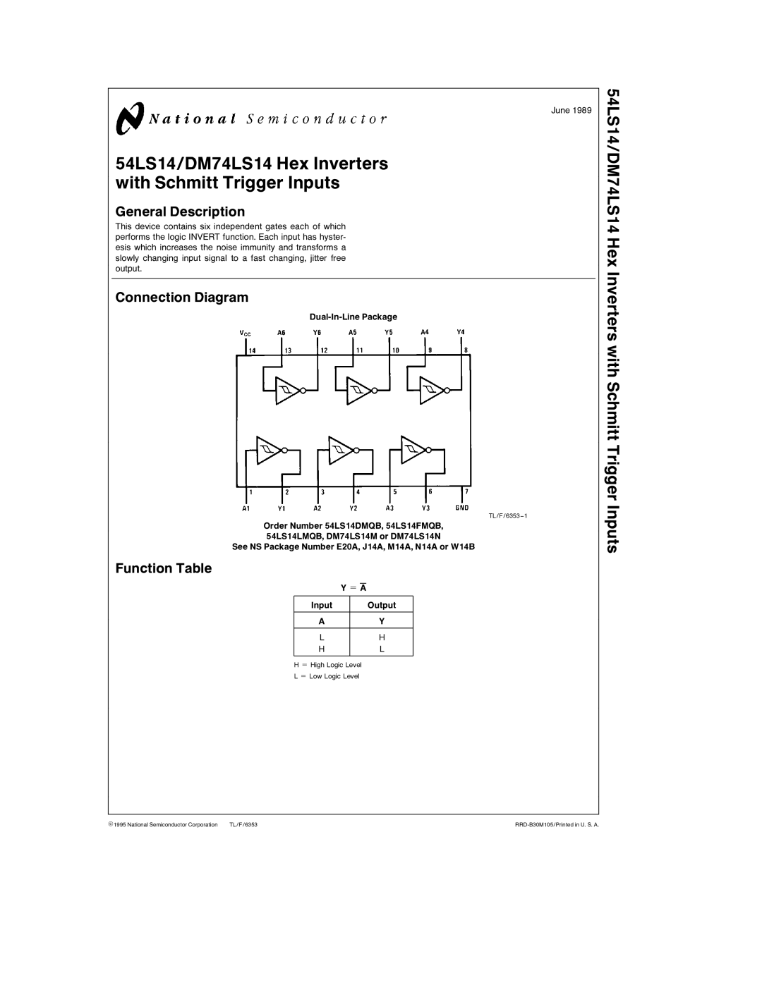
This device contains six independent gates each of which performs the logic INVERT function. Each input has hyster- esis which increases the noise immunity and transforms a slowly changing input signal to a fast changing, jitter free output.
Connection Diagram
TL/F/6353 – 1
Order Number 54LS14DMQB, 54LS14FMQB, 54LS14LMQB, DM74LS14M or DM74LS14N
See NS Package Number E20A, J14A, M14A, N14A or W14B
Function Table
|
|
|
|
|
| Y e A | |||
Input |
|
|
| Output |
|
|
|
|
|
A |
|
|
| Y |
|
|
|
|
|
L |
|
|
| H |
H |
|
|
| L |
|
|
|
|
|
H e High Logic Level
L e Low Logic Level
June 1989
54LS14/DM74LS14 Hex Inverters with Schmitt Trigger Inputs
C1995 National Semiconductor Corporation | TL/F/6353 |
