3. Hold tools by insulated gripping sur- |
faces when performing an operation |
where the cutting tool may contact |
ASSEMBLY
hidden wiring or its own cord. Con- |
tact with a “live” wire will make exposed |
metal parts of the tool “live” and shock |
the operator. |
4. Keep hands away from all cutting |
edges and moving parts. |
SymbologySpecifications
![]() WARNING
WARNING
Recharge only with the charger specified for the battery. For spe- cific charging instructions, read the operator’s manual supplied with your charger and battery.
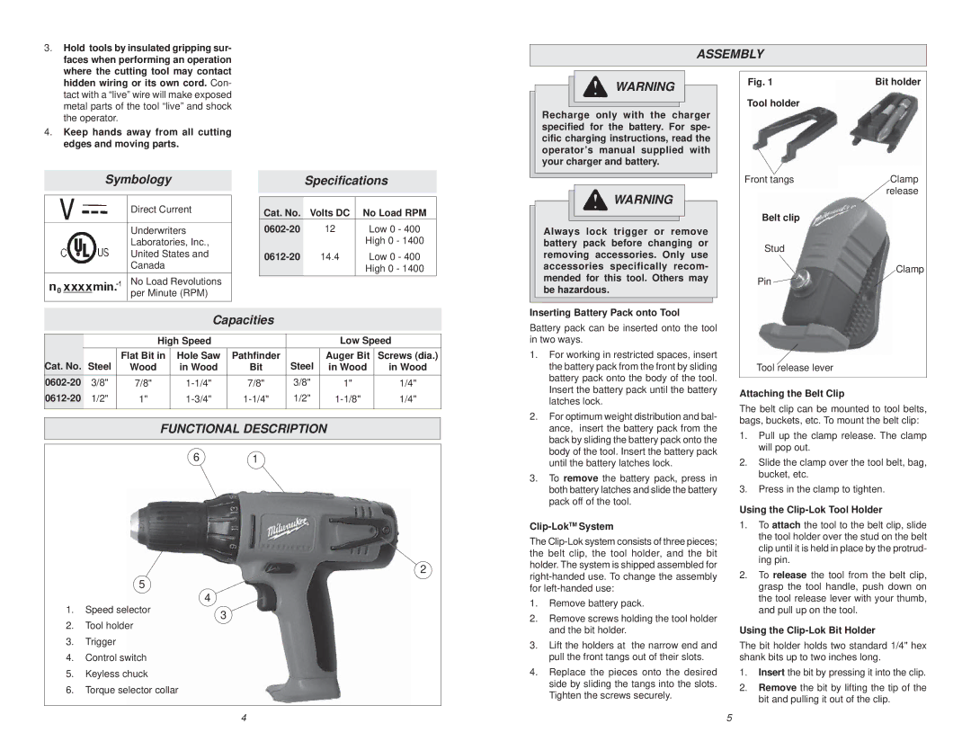
Fig. 1 | Bit holder |
Tool holder
Front tangs | Clamp |
Direct Current
Underwriters
Laboratories, Inc.,
United States and
Canada
No Load Revolutions per Minute (RPM)
Cat. No. | Volts DC | No Load RPM |
12 | Low 0 - 400 | |
|
| High 0 - 1400 |
14.4 | Low 0 - 400 | |
|
| High 0 - 1400 |
![]() WARNING
WARNING
Always lock trigger or remove battery pack before changing or removing accessories. Only use accessories specifically recom- mended for this tool. Others may be hazardous.
release |
Belt clip |
Stud |
Clamp |
Pin |
Capacities
|
| High Speed |
|
| Low Speed | ||
Cat. No. | Steel | Flat Bit in | Hole Saw | Pathfinder | Steel | Auger Bit | Screws (dia.) |
Wood | in Wood | Bit | in Wood | in Wood | |||
3/8" | 7/8" | 7/8" | 3/8" | 1" | 1/4" | ||
1/2" | 1" | 1/2" | 1/4" | ||||
|
|
|
|
|
|
|
|
FUNCTIONAL DESCRIPTION
6 1
Inserting Battery Pack onto Tool
Battery pack can be inserted onto the tool in two ways.
1.For working in restricted spaces, insert the battery pack from the front by sliding battery pack onto the body of the tool. Insert the battery pack until the battery latches lock.
2.For optimum weight distribution and bal- ance, insert the battery pack from the back by sliding the battery pack onto the body of the tool. Insert the battery pack until the battery latches lock.
3.To remove the battery pack, press in both battery latches and slide the battery pack off of the tool.
Tool release lever
Attaching the Belt Clip
The belt clip can be mounted to tool belts, bags, buckets, etc. To mount the belt clip:
1.Pull up the clamp release. The clamp will pop out.
2.Slide the clamp over the tool belt, bag, bucket, etc.
3.Press in the clamp to tighten.
Using the
2
5
4
1. Speed selector | 3 |
|
2.Tool holder
3.Trigger
4.Control switch
5.Keyless chuck
6.Torque selector collar
Clip-LokTM System
The
1.Remove battery pack.
2.Remove screws holding the tool holder and the bit holder.
3.Lift the holders at the narrow end and pull the front tangs out of their slots.
4.Replace the pieces onto the desired side by sliding the tangs into the slots. Tighten the screws securely.
1.To attach the tool to the belt clip, slide the tool holder over the stud on the belt clip until it is held in place by the protrud- ing pin.
2.To release the tool from the belt clip, grasp the tool handle, push down on the tool release lever with your thumb, and pull up on the tool.
Using the Clip-Lok Bit Holder
The bit holder holds two standard 1/4" hex shank bits up to two inches long.
1.Insert the bit by pressing it into the clip.
2.Remove the bit by lifting the tip of the bit and pulling it out of the clip.
4 | 5 |