OPERATION
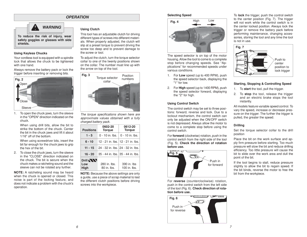
Selecting Speed
To lock the trigger, push the control switch to the center position (Fig. 7). The trigger
WARNING
To reduce the risk of injury, wear safety goggles or glasses with side shields.
Using Keyless Chucks
Your cordless tool is equipped with a spindle lock that allows the chuck to be tightened with one hand.
Always remove the battery pack or lock the trigger before inserting or removing bits.
Fig. 2
Open
Close
Sleeve ![]()
1.To open the chuck jaws, turn the sleeve in the "OPEN" direction indicated on the chuck.
When using drill bits, allow the bit to strike the bottom of the chuck. Center the bit in the chuck jaws and lift it about 1/16" off of the bottom.
When using screwdriver bits, insert the bit far enough for the chuck jaws to grip the hex of the bit.
2.To close the chuck jaws, turn the sleeve in the "CLOSE" direction indicated on the chuck. The bit is secure when the chuck makes a ratcheting sound and the sleeve can not be rotated any further.
NOTE: A ratcheting sound may be heard when the chuck is opened or closed. This noise is part of the locking feature, and does not indicate a problem with the chuck's operation.
Using Clutch
This tool has an adjustable clutch for driving different types of screws into different materi- als. When properly adjusted, the clutch will slip at a preset torque to prevent driving the screw too deep and to prevent damage to the screw or tool.
To adjust the clutch, turn the torque selector collar to one of the twenty positions shown on the collar. The number must line up with the arrow on top of the tool.
Fig. 3 | Torque selector | Position |
| numbers | |
| collar | |
|
|
The torque specifications shown here are approximate values obtained with a fully charged battery pack.
Positions | |||
Torque | Torque | ||
1 | - 5 | 0 - 10 in. lbs. | 0 - 10 in. lbs. |
6 - 10 | 12 - 21 in. lbs. | 12 - 21 in. lbs. | |
11 | - 15 | 24 - 32 in. lbs. | 24 - 32 in. lbs. |
16 | - 20 | 35 - 44 in. lbs. | 35 - 44 in. lbs. |
Drill |
| 280 in. lbs. | 390 in. lbs |
Low |
| ||
High |
| 80 in. lbs. | 100 in. lbs. |
NOTE: Because the above settings are only a guide, use a piece of scrap material to test the different clutch positions before driving screws into the workpiece.
Fig. 4 | High |
| Low |
|
|
| |
|
|
|
|
The speed selector is on top of the motor housing. Allow the tool to come to a complete stop before changing speeds. See “Ap- plications” for recommended speeds under various conditions.
1.For Low speed (up to 400 RPM), push the speed selector back, displaying the "1" for low.
2.For High speed (up to 1400 RPM), push the speed selector forward, displaying the "2" for high.
Using Control Switch
The control switch may be set to three posi- tions: forward, reverse and lock. Due to a lockout mechanism, the control switch can only be adjusted when the ON/OFF switch is not depressed. Always allow the motor to come to a complete stop before using the control switch.
For forward (clockwise) rotation, push in the control switch from the right side of the tool (Fig. 5). Check the direction of rotation before use.
Fig. 5
Push in for forward
For reverse (counterclockwise) rotation, push in the control switch from the left side of the tool (Fig. 6). Check direction of rota- tion before use.
Fig. 6
Push in ![]() for reverse
for reverse
will not work while the control switch is in the center locked position. Always lock the trigger or remove the battery pack before performing maintenance, changing acces- sories, storing the tool and any time the tool is not in use.
Fig. 7
Push to center position to lock trigger
Starting, Stopping & Controlling Speed
1.To start the tool, pull the trigger.
2.To stop the tool, release the trigger and an electric brake stops the tool instantly.
All models feature variable speed control. To vary the speed, increase or decrease pres- sure on the trigger. The further the trigger is pulled, the greater the speed.
Drilling
Set the torque selector collar to the drill position
Place the bit on the work surface and ap- ply firm pressure before starting. Too much pressure will slow the bit and reduce drilling efficiency. Too little pressure will cause the bit to slide over the work area and dull the point of the bit.
If the tool begins to stall, reduce pressure slightly to allow the bit to regain speed. If the bit binds, reverse the motor to free the bit from the workpiece.
6 | 7 |