Terminal Panel
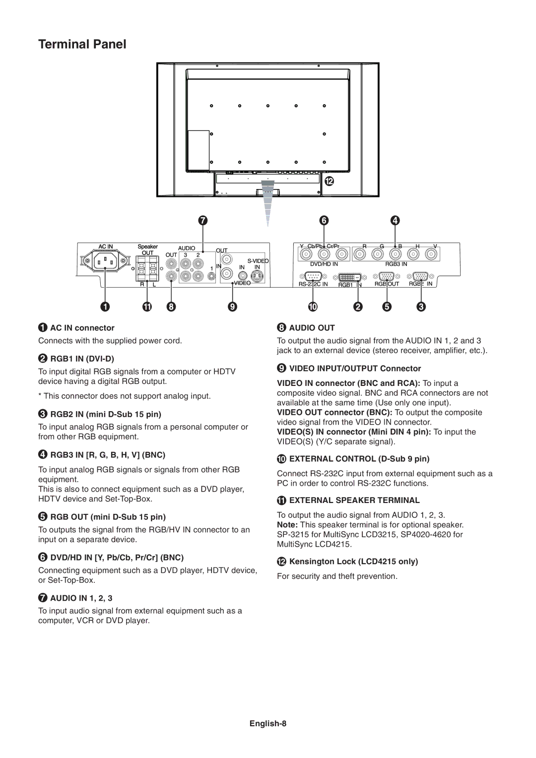
1AC IN connector
Connects with the supplied power cord.
2RGB1 IN (DVI-D)
To input digital RGB signals from a computer or HDTV device having a digital RGB output.
* This connector does not support analog input.
3RGB2 IN (mini
To input analog RGB signals from a personal computer or from other RGB equipment.
4RGB3 IN [R, G, B, H, V] (BNC)
To input analog RGB signals or signals from other RGB equipment.
This is also to connect equipment such as a DVD player, HDTV device and
5RGB OUT (mini
To outputs the signal from the RGB/HV IN connector to an input on a separate device.
6DVD/HD IN [Y, Pb/Cb, Pr/Cr] (BNC)
Connecting equipment such as a DVD player, HDTV device, or
7AUDIO IN 1, 2, 3
To input audio signal from external equipment such as a computer, VCR or DVD player.
8AUDIO OUT
To output the audio signal from the AUDIO IN 1, 2 and 3 jack to an external device (stereo receiver, amplifier, etc.).
9VIDEO INPUT/OUTPUT Connector
VIDEO IN connector (BNC and RCA): To input a composite video signal. BNC and RCA connectors are not available at the same time (Use only one input).
VIDEO OUT connector (BNC): To output the composite video signal from the VIDEO IN connector.
VIDEO(S) IN connector (Mini DIN 4 pin): To input the VIDEO(S) (Y/C separate signal).
10EXTERNAL CONTROL
Connect
11EXTERNAL SPEAKER TERMINAL
To output the audio signal from AUDIO 1, 2, 3. Note: This speaker terminal is for optional speaker.
12Kensington Lock (LCD4215 only)
For security and theft prevention.