Parts Name and Functions
Front Panel
POWER |
|
| LED DISPLAY OUTPUT |
|
| DVI | |||||||||
1 |
| 2 |
| 3 |
| 4 |
| 5 |
| 6 |
| 7 |
| 8 | OUT IN RS- 4 8 5 |
|
|
|
|
|
|
| |||||||||
POWER |
|
| LED DISPLAY OUTPUT |
|
|
| DVI | ||||||||||
|
| 1 |
| 2 |
| 3 |
| 4 |
| 5 |
| 6 |
| 7 |
| 8 | OUT IN RS- 485 |
| |||||||||||||||||
|
|
|
|
|
|
|
|
| |||||||||
123 4 5
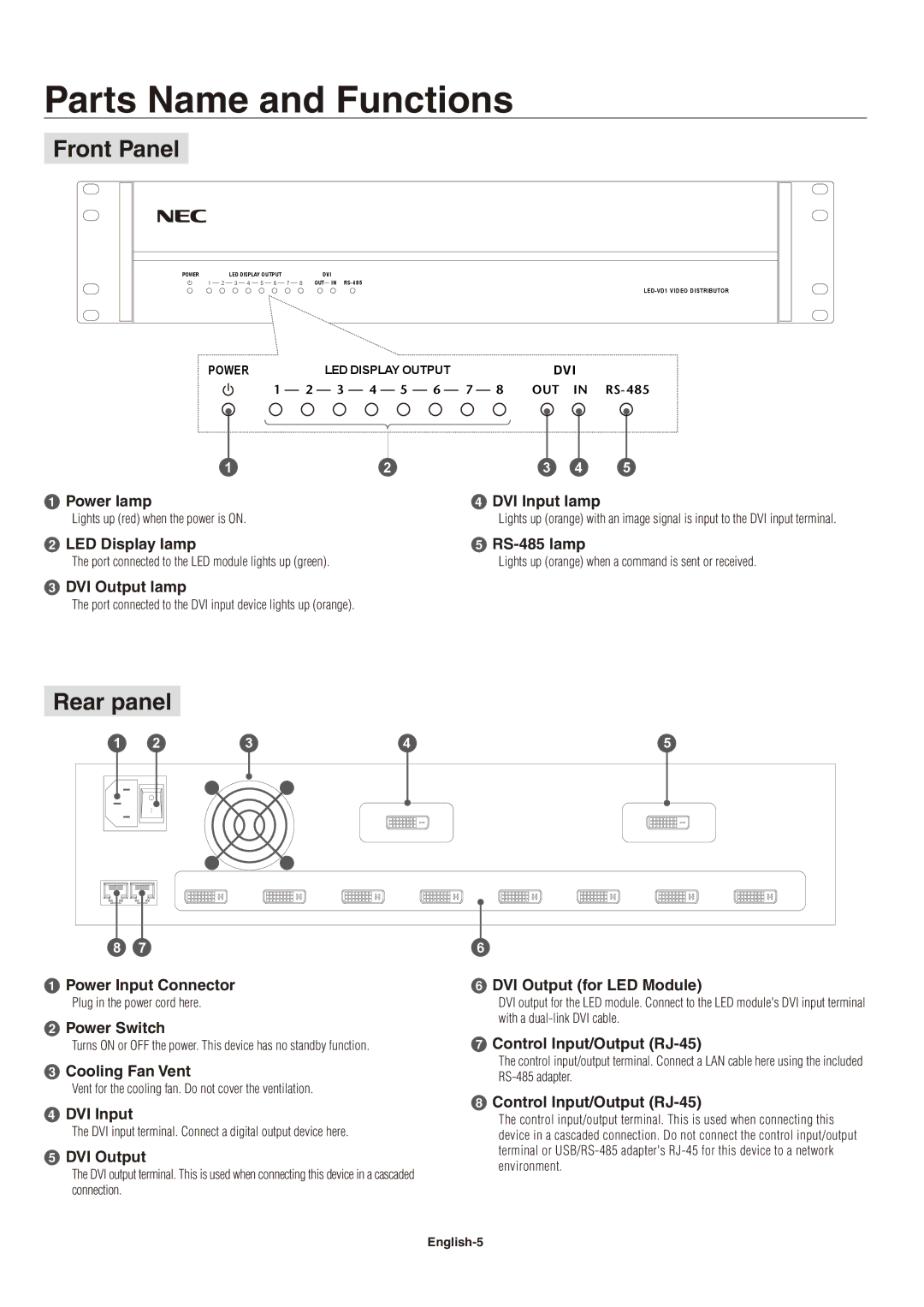
1 Power lamp | 4 DVI Input lamp |
Lights up (red) when the power is ON. | Lights up (orange) with an image signal is input to the DVI input terminal. |
2 LED Display lamp | 5 |
The port connected to the LED module lights up (green). | Lights up (orange) when a command is sent or received. |
3 DVI Output lamp
The port connected to the DVI input device lights up (orange).
Rear panel
1 | 2 | 3 | 4 | 5 |
8 | 7 |
|
| 6 |
1 Power Input Connector
Plug in the power cord here.
2 Power Switch
Turns ON or OFF the power. This device has no standby function.
3 Cooling Fan Vent
Vent for the cooling fan. Do not cover the ventilation.
4 DVI Input
The DVI input terminal. Connect a digital output device here.
5 DVI Output
The DVI output terminal. This is used when connecting this device in a cascaded connection.
6 DVI Output (for LED Module)
DVI output for the LED module. Connect to the LED module's DVI input terminal with a
7 Control Input/Output
The control input/output terminal. Connect a LAN cable here using the included
8 Control Input/Output
The control input/output terminal. This is used when connecting this device in a cascaded connection. Do not connect the control input/output terminal or