4xN 10/100/1000 Span Port iMatrix Switch
Product Diagrams
|
|
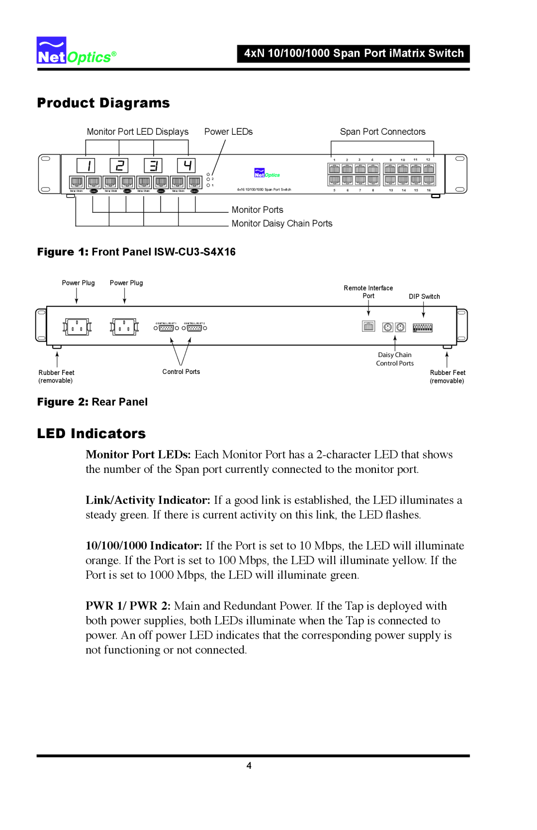
| Monitor Port LED Displays | Power LEDs |
|
| Span Port Connectors |
|
| |||||||||||||||||||||
|
|
|
|
|
|
|
|
|
|
|
|
|
|
|
|
|
|
|
|
|
|
|
|
|
|
|
|
|
| |
|
|
|
|
|
|
|
|
|
|
|
|
|
|
|
|
|
|
|
|
|
|
|
|
|
|
|
|
|
|
|
|
|
|
|
|
|
|
|
|
|
|
|
|
|
|
|
| 2 |
|
| 1 | 2 | 3 | 4 | 9 | 10 | 11 | 12 |
| ||
|
|
|
|
|
|
|
|
|
|
|
|
|
|
|
|
|
|
|
|
|
|
|
|
|
|
|
|
|
| |
|
|
|
|
|
|
|
|
|
|
|
|
|
|
|
|
|
|
|
|
|
|
|
|
|
|
|
|
|
| |
|
|
|
|
|
|
|
|
|
|
|
|
|
|
|
|
|
|
|
|
|
|
|
|
|
|
|
|
|
| |
|
|
|
|
|
|
|
|
|
|
|
|
|
|
|
|
| 1 |
|
|
|
|
|
|
|
|
|
|
|
|
|
|
|
|
|
|
|
|
|
|
|
|
|
|
|
|
|
|
|
|
|
|
|
|
|
|
|
|
| |||
| Daisy Chain Monitor 1 Daisy Chain Monitor 2 Daisy Chain Monitor 3 Daisy Chain Monitor 4 | 4x16 10/100/1000 Span Port Switch | 5 | 6 | 7 | 8 | 13 | 14 | 15 | 16 |
| |||||||||||||||||||
Monitor Ports
Monitor Daisy Chain Ports
Figure 1: Front Panel ISW-CU3-S4X16
Power Plug | Power Plug | Remote Interface | |
|
| ||
|
| Port | DIP Switch |
|
| CONTROL PORT 1 CONTROL PORT 2 | 1 2 3 4 5 6 7 8 |
|
|
| OFF |
|
|
| Daisy Chain |
|
|
| Control Ports |
Rubber Feet |
| Control Ports | Rubber Feet |
(removable) |
|
| (removable) |
Figure 2: Rear Panel
LED Indicators
Monitor Port LEDs: Each Monitor Port has a
Link/Activity Indicator: If a good link is established, the LED illuminates a steady green. If there is current activity on this link, the LED flashes.
10/100/1000 Indicator: If the Port is set to 10 Mbps, the LED will illuminate orange. If the Port is set to 100 Mbps, the LED will illuminate yellow. If the Port is set to 1000 Mbps, the LED will illuminate green.
PWR 1/ PWR 2: Main and Redundant Power. If the Tap is deployed with both power supplies, both LEDs illuminate when the Tap is connected to power. An off power LED indicates that the corresponding power supply is not functioning or not connected.
4