LEDs
The table below describes the activity of the LEDs.
Label | Color | Activity | Description |
|
|
|
|
Pwr (Power) | Green | On | Power is supplied to the hub. |
|
|
|
|
Col (collision) | Amber | Blinking | Data collision is occurring on the network. Note |
|
|
| that occasional collisions are normal. |
|
|
|
|
Link | Green | On | The link between this port and the connected |
(on the top |
|
| device is good. |
right corner of |
|
|
|
each vista |
|
|
|
|
|
| |
port) |
|
|
|
|
|
|
|
Rx | Green | Blinking | There is incoming data on the port. |
(on the top |
|
|
|
right corner of |
|
|
|
each vista |
|
|
|
|
|
| |
port) |
|
|
|
|
|
|
|
Normal/Uplink Push Button
The Normal/Uplink push button allows you to select Normal
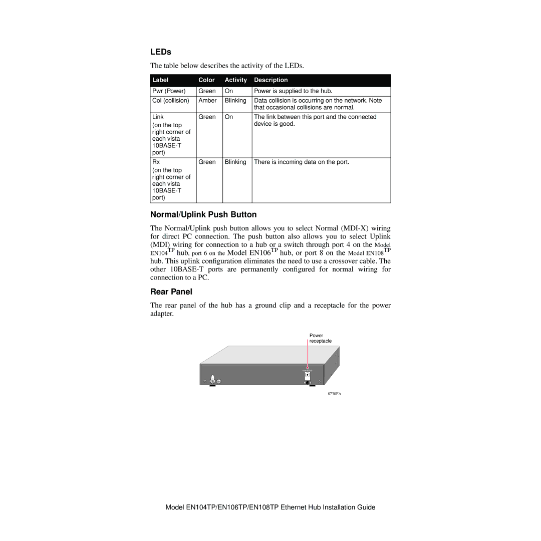
Rear Panel
The rear panel of the hub has a ground clip and a receptacle for the power adapter.
Power receptacle
5Vdc 800mA
— ![]() +
+
8730FA
Model EN104TP/EN106TP/EN108TP Ethernet Hub Installation Guide