establish a link with non-stacking interfaces no traffic will pass across the interface. These interfaces are available to quickly and easily build a stack of switches by simply connecting two or more FSM7300 switches together with either Category 5 copper Ethernet cables or with SFP-based fiber connections.
•After ascertaining this information, the switch automatically configures the RJ-45 port to enable communications with the attached device, without requiring user intervention. In this way, the Auto Uplink technology eliminates the need for setting uplink connections or being concerned about whether to use crossover or straight-through cables when attaching devices.
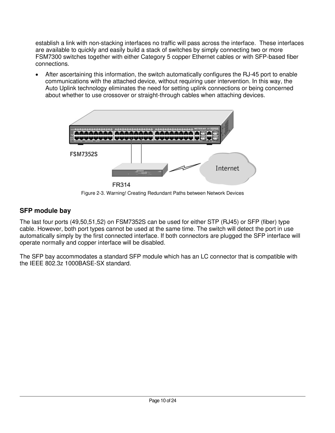
Figure 2-3. Warning! Creating Redundant Paths between Network Devices
SFP module bay
The last four ports (49,50,51,52) on FSM7352S can be used for either STP (RJ45) or SFP (fiber) type cable. However, both port types cannot be used at the same time. The switch will detect the port in use automatically simply by the first connected interface. If both connectors are plugged the SFP interface will operate normally and copper interface will be disabled.
The SFP bay accommodates a standard SFP module which has an LC connector that is compatible with the IEEE 802.3z 1000BASE-SX standard.
Page 10 of 24