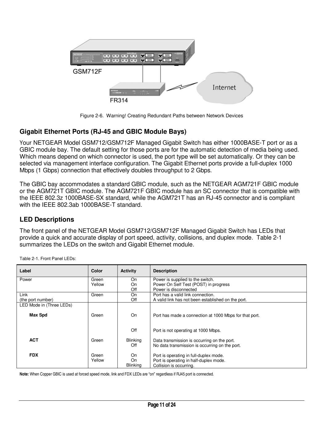
Figure
Gigabit Ethernet Ports (RJ-45 and GBIC Module Bays)
Your NETGEAR Model GSM712/GSM712F Managed Gigabit Switch has either
The GBIC bay accommodates a standard GBIC module, such as the NETGEAR AGM721F GBIC module or the AGM721T GBIC module. The AGM721F GBIC module has an SC connector that is compatible with the IEEE 802.3z
LED Descriptions
The front panel of the NETGEAR Model GSM712/GSM712F Managed Gigabit Switch has LEDs that provide a quick and accurate display of port speed, activity, collisions, and duplex mode. Table
Table
Label | Color | Activity | Description |
|
|
|
|
Power | Green | On | Power is supplied to the switch. |
| Yellow | On | Power On Self Test (POST) in progress |
|
| Off | Power is disconnected |
Link | Green | On | Port has a valid link connection. |
(the port number) |
| Off | A valid link has not been established on the port. |
LED Mode in (Three LEDs) |
|
|
|
Max Spd | Green | On | Port has made a connection at 1000 Mbps for that port. |
|
| Off | Port is not operating at 1000 Mbps. |
ACT | Green | Blinking | Data transmission is occurring on the port. |
|
| Off | No data transmission is occurring on the port. |
FDX | Green | On | Port is operating in |
| Yellow | On | Port is operating in |
|
| Blinking | Collision is occurring. |
Note: When Copper GBIC is used at forced speed mode, link and FDX LEDs are “on” regardless if RJ45 port is connected.
Page 11 of 24