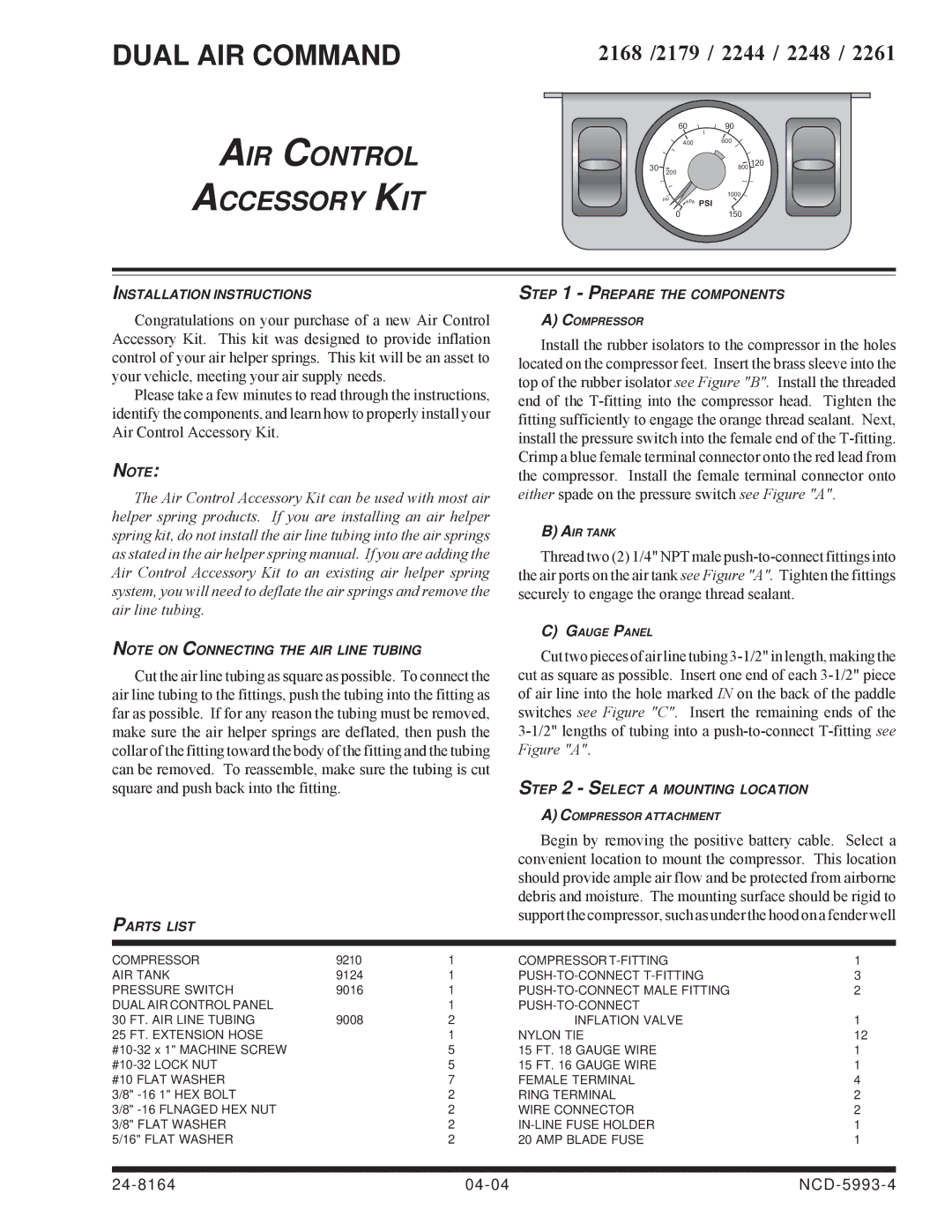
DUAL AIR COMMAND
AIR CONTROL
ACCESSORY KIT
2168 /2179 / 2244 / 2248 / 2261
|
| 60 | 90 |
|
| 400 | 600 |
|
|
| |
30 | 200 |
| 800 120 |
| psi |
| 1000 |
| kPa | PSI | |
|
|
0150
INSTALLATION INSTRUCTIONS
Congratulations on your purchase of a new Air Control Accessory Kit. This kit was designed to provide inflation control of your air helper springs. This kit will be an asset to your vehicle, meeting your air supply needs.
Please take a few minutes to read through the instructions, identify the components, and learn how to properly install your Air Control Accessory Kit.
NOTE:
The Air Control Accessory Kit can be used with most air helper spring products. If you are installing an air helper spring kit, do not install the air line tubing into the air springs as stated in the air helper spring manual. If you are adding the Air Control Accessory Kit to an existing air helper spring system, you will need to deflate the air springs and remove the air line tubing.
NOTE ON CONNECTING THE AIR LINE TUBING
Cut the air line tubing as square as possible. To connect the air line tubing to the fittings, push the tubing into the fitting as far as possible. If for any reason the tubing must be removed, make sure the air helper springs are deflated, then push the collar of the fitting toward the body of the fitting and the tubing can be removed. To reassemble, make sure the tubing is cut square and push back into the fitting.
STEP 1 - PREPARE THE COMPONENTS
A)COMPRESSOR
Install the rubber isolators to the compressor in the holes located on the compressor feet. Insert the brass sleeve into the top of the rubber isolator see Figure "B". Install the threaded end of the
B)AIR TANK
Thread two (2) 1/4" NPT male
C)GAUGE PANEL
Cut two pieces of air line tubing
STEP 2 - SELECT A MOUNTING LOCATION
A)COMPRESSOR ATTACHMENT
|
|
| Begin by removing the positive battery cable. Select a | |
|
|
| convenient location to mount the compressor. This location | |
|
|
| should provide ample air flow and be protected from airborne | |
|
|
| debris and moisture. The mounting surface should be rigid to | |
PARTS LIST |
|
| support the compressor, such as under the hood on a fender well | |
|
|
|
| |
|
|
|
|
|
COMPRESSOR | 9210 | 1 | COMPRESSOR | 1 |
AIR TANK | 9124 | 1 | 3 | |
PRESSURE SWITCH | 9016 | 1 | 2 | |
DUAL AIR CONTROL PANEL |
| 1 |
| |
30 FT. AIR LINE TUBING | 9008 | 2 | INFLATION VALVE | 1 |
25 FT. EXTENSION HOSE |
| 1 | NYLON TIE | 12 |
| 5 | 15 FT. 18 GAUGE WIRE | 1 | |
| 5 | 15 FT. 16 GAUGE WIRE | 1 | |
#10 FLAT WASHER |
| 7 | FEMALE TERMINAL | 4 |
3/8" |
| 2 | RING TERMINAL | 2 |
3/8" |
| 2 | WIRE CONNECTOR | 2 |
3/8" FLAT WASHER |
| 2 | 1 | |
5/16" FLAT WASHER |
| 2 | 20 AMP BLADE FUSE | 1 |
