BRASS SLEEVE
COMPRESSOR
![]() FOOT
FOOT
![]()
![]() RUBBER
RUBBER
ISOLATOR
#10 | #10 FLAT WASHER |
NUT | BRASS SLEEVE |
|
COMPRESSOR
![]() FOOT
FOOT
![]() RUBBER
RUBBER
ISOLATOR
VEHICLE
MOUNTING
SURFACE
#10 FLAT WASHER | ||
SCREW | ||
|
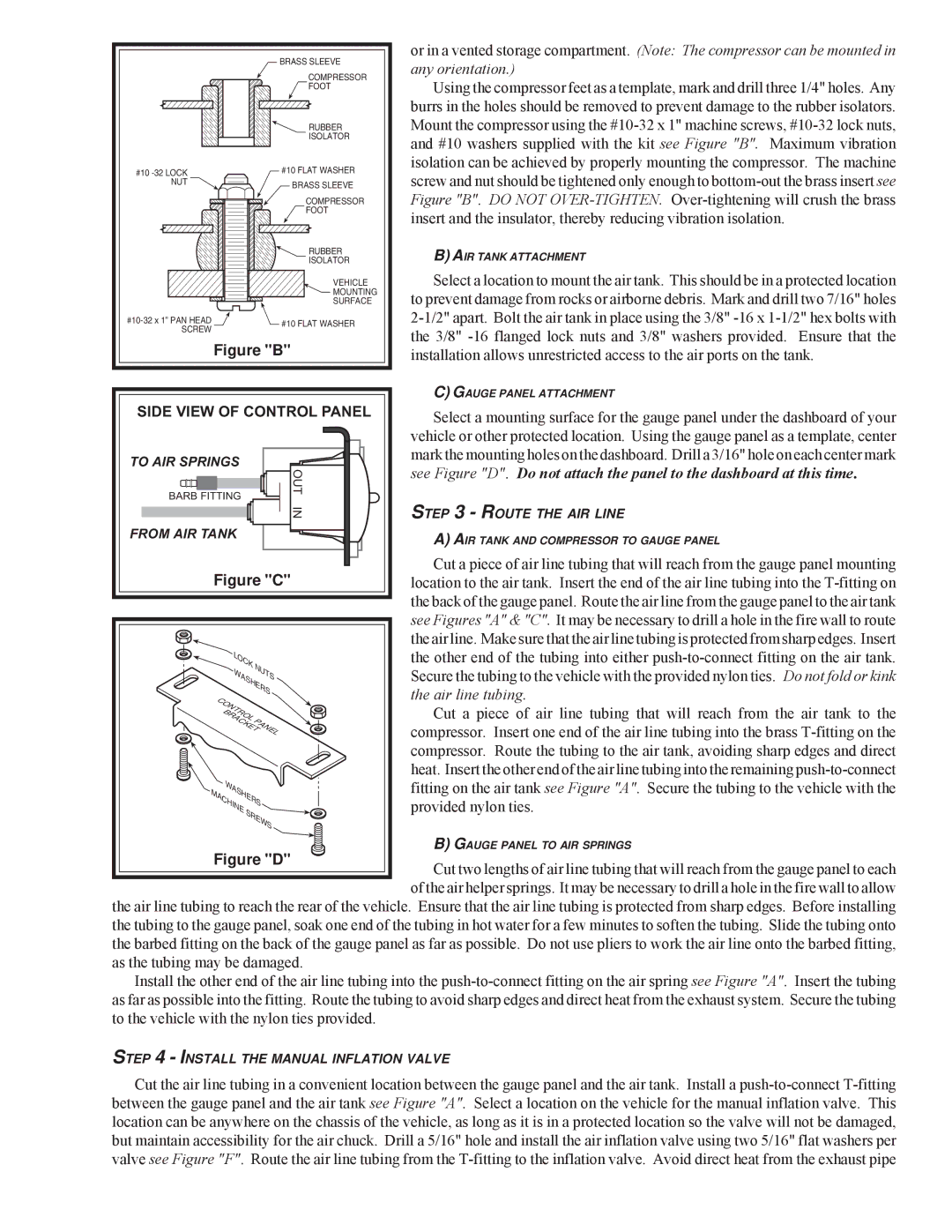
Figure "B"
SIDE VIEW OF CONTROL PANEL
or in a vented storage compartment. (Note: The compressor can be mounted in any orientation.)
Using the compressor feet as a template, mark and drill three 1/4" holes. Any burrs in the holes should be removed to prevent damage to the rubber isolators. Mount the compressor using the
B)AIR TANK ATTACHMENT
Select a location to mount the air tank. This should be in a protected location to prevent damage from rocks or airborne debris. Mark and drill two 7/16" holes
C)GAUGE PANEL ATTACHMENT
Select a mounting surface for the gauge panel under the dashboard of your vehicle or other protected location. Using the gauge panel as a template, center
TO AIR SPRINGS
BARB FITTING
FROM AIR TANK
OUT |
IN |
mark the mounting holes on the dashboard. Drill a 3/16" hole on each center mark see Figure "D". Do not attach the panel to the dashboard at this time.
STEP 3 - ROUTE THE AIR LINE
A)AIR TANK AND COMPRESSOR TO GAUGE PANEL
Cut a piece of air line tubing that will reach from the gauge panel mounting location to the air tank. Insert the end of the air line tubing into the
Cut a piece of air line tubing that will reach from the air tank to the compressor. Insert one end of the air line tubing into the brass
B) GAUGE PANEL TO AIR SPRINGS
Cut two lengths of air line tubing that will reach from the gauge panel to each of the air helper springs. It may be necessary to drill a hole in the fire wall to allow the air line tubing to reach the rear of the vehicle. Ensure that the air line tubing is protected from sharp edges. Before installing
the tubing to the gauge panel, soak one end of the tubing in hot water for a few minutes to soften the tubing. Slide the tubing onto the barbed fitting on the back of the gauge panel as far as possible. Do not use pliers to work the air line onto the barbed fitting, as the tubing may be damaged.
Install the other end of the air line tubing into the
STEP 4 - INSTALL THE MANUAL INFLATION VALVE
Cut the air line tubing in a convenient location between the gauge panel and the air tank. Install a