AIR LINE |
FLAT WASHER |
INFLATION VALVE |
BODY OF |
VEHICLE |
HEX NUT |
VALVE CAP |
|
|
|
| ST | IC |
| ||
|
| LA |
| OR |
| |||
P |
| CT |
| |||||
| N | E |
|
|
|
| ||
O | N |
|
|
|
|
| ||
|
|
|
|
|
| |||
C |
|
|
|
|
|
|
|
|
CONNECTING |
| EXISTING | ||||||
WIRE | WIRE | |||||||
|
|
|
|
|
|
|
| |
FUSE HOLDER
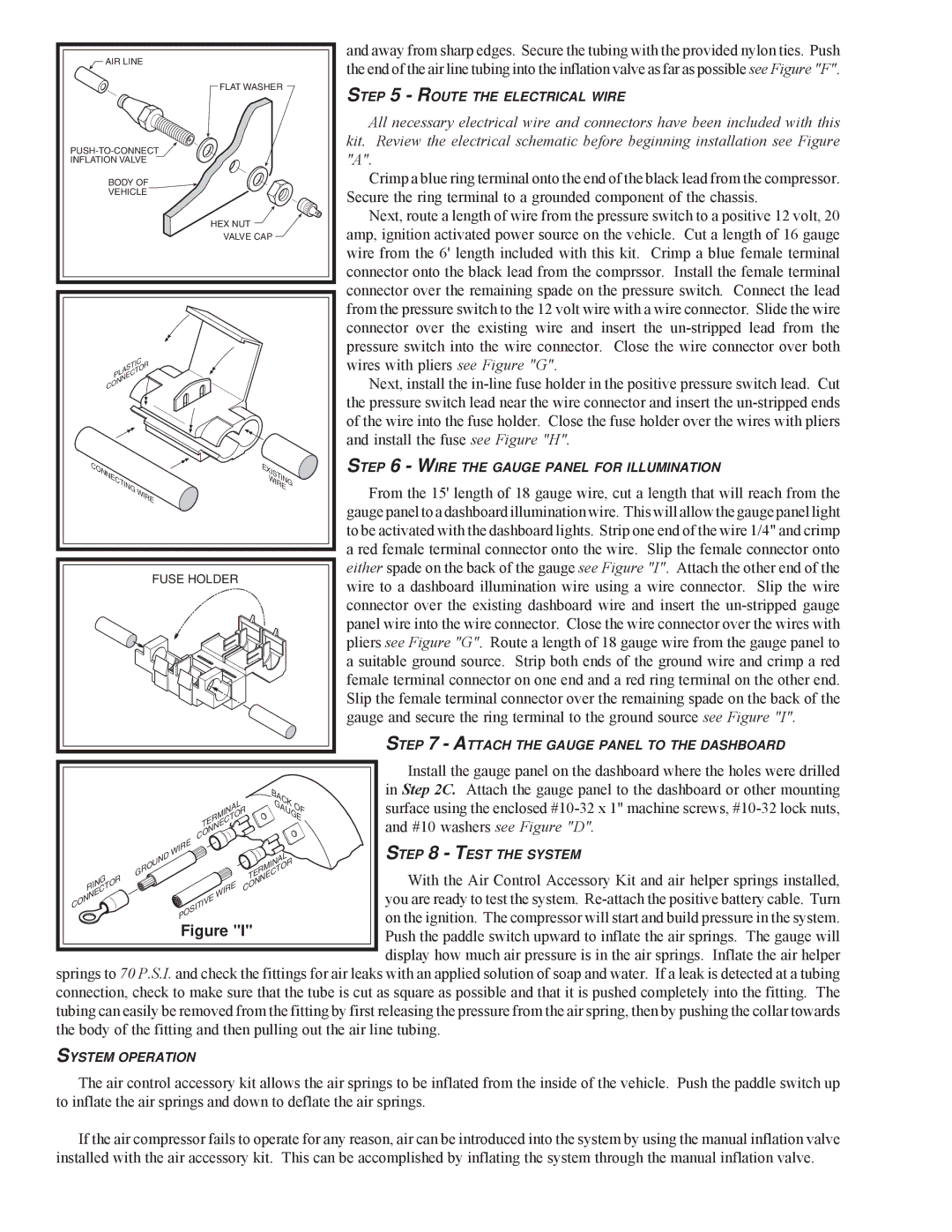
and away from sharp edges. Secure the tubing with the provided nylon ties. Push the end of the air line tubing into the inflation valve as far as possible see Figure "F".
STEP 5 - ROUTE THE ELECTRICAL WIRE
All necessary electrical wire and connectors have been included with this kit. Review the electrical schematic before beginning installation see Figure "A".
Crimp a blue ring terminal onto the end of the black lead from the compressor. Secure the ring terminal to a grounded component of the chassis.
Next, route a length of wire from the pressure switch to a positive 12 volt, 20 amp, ignition activated power source on the vehicle. Cut a length of 16 gauge wire from the 6' length included with this kit. Crimp a blue female terminal connector onto the black lead from the comprssor. Install the female terminal connector over the remaining spade on the pressure switch. Connect the lead from the pressure switch to the 12 volt wire with a wire connector. Slide the wire connector over the existing wire and insert the
Next, install the
STEP 6 - WIRE THE GAUGE PANEL FOR ILLUMINATION
From the 15' length of 18 gauge wire, cut a length that will reach from the gauge panel to a dashboard illumination wire. This will allow the gauge panel light to be activated with the dashboard lights. Strip one end of the wire 1/4" and crimp a red female terminal connector onto the wire. Slip the female connector onto either spade on the back of the gauge see Figure "I". Attach the other end of the wire to a dashboard illumination wire using a wire connector. Slip the wire connector over the existing dashboard wire and insert the
STEP 7 - ATTACH THE GAUGE PANEL TO THE DASHBOARD
TERMINAL CONNECTOR
BACK ![]()
![]()
![]() GAUGEOF
GAUGEOF
Install the gauge panel on the dashboard where the holes were drilled in Step 2C. Attach the gauge panel to the dashboard or other mounting surface using the enclosed
| WIRE |
| STEP 8 - TEST THE SYSTEM |
GROUND |
| TERMINAL | |
| With the Air Control Accessory Kit and air helper springs installed, | ||
RING | WIRE | CONNECTOR | |
CONNECTOR |
| you are ready to test the system. | |
POSITIVE |
| ||
|
| on the ignition. The compressor will start and build pressure in the system. | |
| Figure "I" | ||
| Push the paddle switch upward to inflate the air springs. The gauge will | ||
|
|
| display how much air pressure is in the air springs. Inflate the air helper |
springs to 70 P.S.I. and check the fittings for air leaks with an applied solution of soap and water. If a leak is detected at a tubing connection, check to make sure that the tube is cut as square as possible and that it is pushed completely into the fitting. The tubing can easily be removed from the fitting by first releasing the pressure from the air spring, then by pushing the collar towards the body of the fitting and then pulling out the air line tubing.
SYSTEM OPERATION
The air control accessory kit allows the air springs to be inflated from the inside of the vehicle. Push the paddle switch up to inflate the air springs and down to deflate the air springs.
If the air compressor fails to operate for any reason, air can be introduced into the system by using the manual inflation valve installed with the air accessory kit. This can be accomplished by inflating the system through the manual inflation valve.