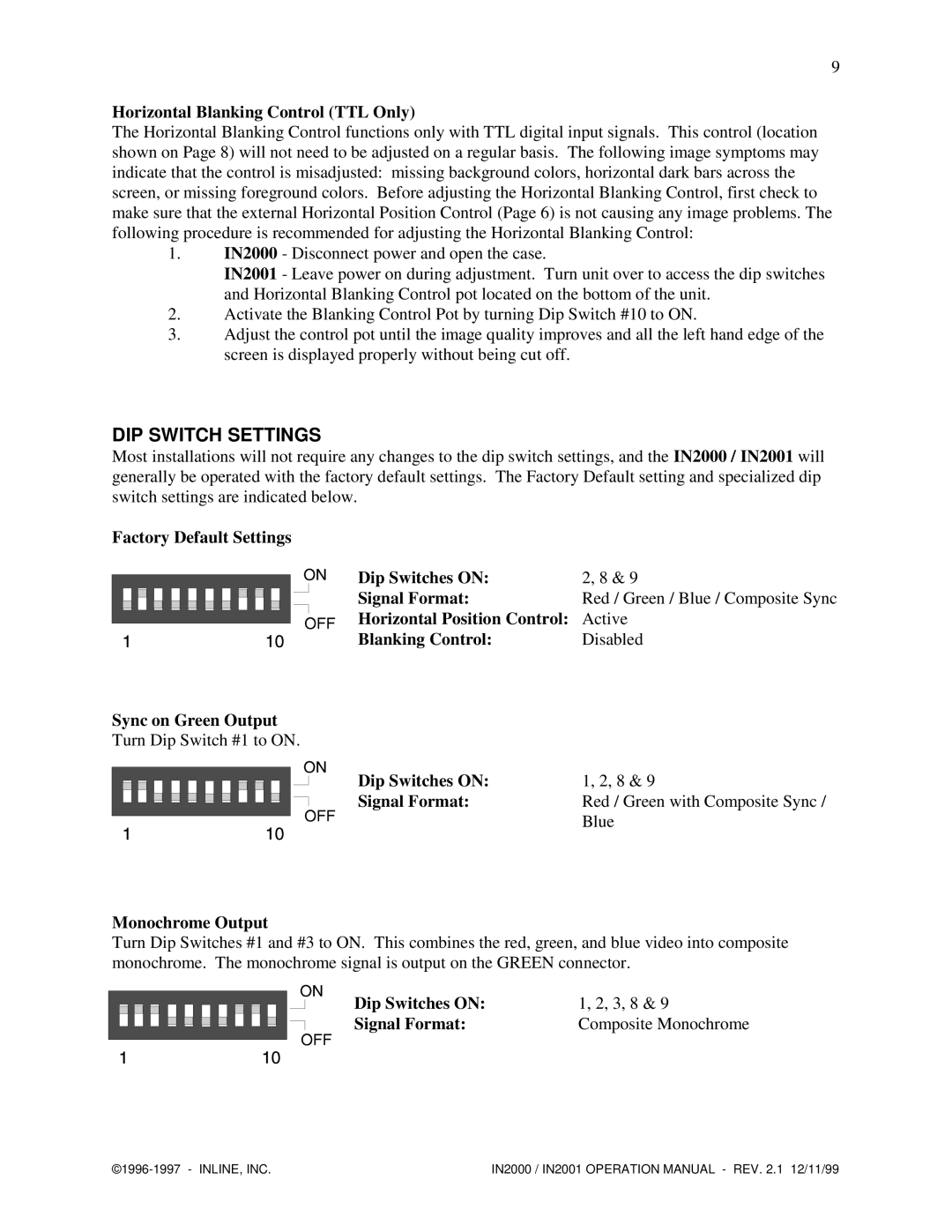
IN2000, IN2001 specifications
Network Computing Devices IN2001 and IN2000 are innovative solutions designed to enhance network performance and the user experience in the realm of enterprise computing. Both devices are tailored to meet the needs of businesses that require reliable, efficient, and scalable network capabilities.The IN2001 is considered a powerhouse in network computing, boasting advanced processing capabilities that allow for high-speed data transmission. One of its main features is its multi-threaded architecture, which enables it to handle multiple operations simultaneously without compromising on speed or efficiency. This makes the IN2001 suitable for environments with heavy data traffic, such as data centers and corporate networks. The device is equipped with built-in redundancy features, ensuring minimal downtime and increased reliability.
On the other hand, the IN2000 caters to smaller businesses or branch offices that require a balance between performance and affordability. It is designed with a user-friendly interface that simplifies configuration and management, making it accessible for IT teams with varying levels of expertise. The IN2000 supports various mounting options and integrates seamlessly with existing infrastructure, allowing for easy deployment.
Both devices leverage cutting-edge technologies, including advanced routing protocols and security measures. They support IPv6, ensuring compatibility with the latest internet standards and future-proofing the network infrastructure. Additionally, the network computing devices are equipped with robust firewall capabilities, helping to protect sensitive data and prevent unauthorized access.
A distinguishing characteristic of the IN2001 is its high scalability, allowing businesses to expand their networks effortlessly as their needs grow. It supports a wide range of connectivity options, including Ethernet and wireless capabilities, providing flexibility for diverse networking environments.
Conversely, the IN2000 focuses on energy efficiency, employing intelligent power management to reduce operational costs. It is designed to be eco-friendly, minimizing its carbon footprint while maintaining optimal performance levels.
In summary, both the IN2001 and IN2000 serve as critical components in modern networking solutions, addressing the unique needs of different business environments. Their combination of performance, versatility, and security makes them ideal choices for organizations looking to enhance their network infrastructure in an ever-evolving digital landscape.

