Operation
Status LEDs
The
PWR | (Power) |
|
|
| On = Connection to external power. | ||
LK1 | (Fiber Link - Port 1) | On = Fiber port 1 is receiving a signal. | |||||
LK2 | (Fiber Link - Port 2) | On = Fiber port 2 is receiving a signal. | |||||
|
|
|
|
|
|
| |
PWR |
|
|
|
|
| ||
LK1 |
|
|
|
|
|
|
|
|
|
|
|
|
|
| |
LK2 | Port 1 | Port 2 | |||||
|
|
| |||||
|
|
|
|
|
|
|
|
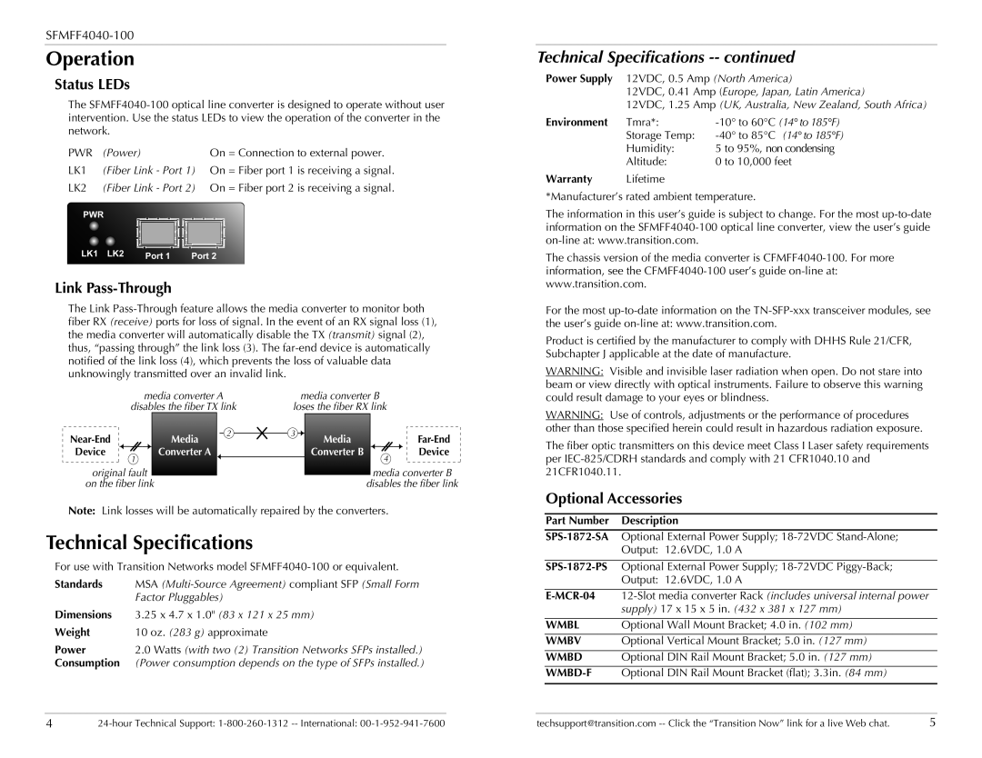
Link Pass-Through
The Link
| media converter A |
|
| media converter B | ||||||||
| disables the fiber TX link | loses the fiber RX link | ||||||||||
| Media |
|
| 2 | 3 |
| Media |
|
|
| ||
|
|
|
|
|
|
|
| |||||
Device | 1 | Converter A |
|
|
|
|
| Converter B |
| 4 |
| Device |
|
|
|
|
|
|
|
|
|
|
| ||
original fault |
|
|
|
|
|
|
| media converter B | ||||
|
|
|
|
|
|
| ||||||
on the fiber link |
|
|
|
| disables the fiber link | |||||||
Note: Link losses will be automatically repaired by the converters.
Technical Specifications
For use with Transition Networks model
Standards | MSA |
| Factor Pluggables) |
Dimensions | 3.25 x 4.7 x 1.0" (83 x 121 x 25 mm) |
Weight | 10 oz. (283 g) approximate |
Power | 2.0 Watts (with two (2) Transition Networks SFPs installed.) |
Consumption | (Power consumption depends on the type of SFPs installed.) |
Technical Specifications -- continued
Power Supply | 12VDC, 0.5 Amp (North America) | |
| 12VDC, 0.41 Amp (Europe, Japan, Latin America) | |
| 12VDC, 1.25 Amp (UK, Australia, New Zealand, South Africa) | |
Environment | Tmra*: | |
| Storage Temp: | |
| Humidity: | 5 to 95%, non condensing |
| Altitude: | 0 to 10,000 feet |
Warranty | Lifetime |
|
*Manufacturer’s rated ambient temperature.
The information in this user’s guide is subject to change. For the most
The chassis version of the media converter is
For the most
Product is certified by the manufacturer to comply with DHHS Rule 21/CFR, Subchapter J applicable at the date of manufacture.
WARNING: Visible and invisible laser radiation when open. Do not stare into beam or view directly with optical instruments. Failure to observe this warning could result damage to your eyes or blindness.
WARNING: Use of controls, adjustments or the performance of procedures other than those specified herein could result in hazardous radiation exposure.
The fiber optic transmitters on this device meet Class I Laser safety requirements per
Optional Accessories
Part Number | Description |
|
|
Optional External Power Supply; | |
| Output: 12.6VDC, 1.0 A |
|
|
Optional External Power Supply; | |
| Output: 12.6VDC, 1.0 A |
|
|
| |
| supply) 17 x 15 x 5 in. (432 x 381 x 127 mm) |
|
|
WMBL | Optional Wall Mount Bracket; 4.0 in. (102 mm) |
|
|
WMBV | Optional Vertical Mount Bracket; 5.0 in. (127 mm) |
|
|
WMBD | Optional DIN Rail Mount Bracket; 5.0 in. (127 mm) |
|
|
| Optional DIN Rail Mount Bracket (flat); 3.3in. (84 mm) |
|
|
4 | techsupport@transition.com | 5 |