Wiring Diagrams
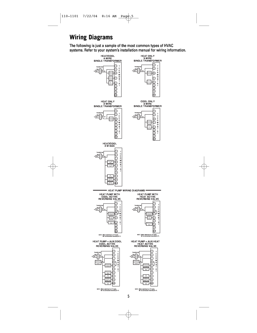
The following is just a sample of the most common types of HVAC systems. Refer to your system’s installation manual for wiring information.
HEAT/COOL | HEAT ONLY |
SINGLE TRANSFORMER | SINGLE TRANSFORMER |
Transformer
Hot
120 VAC | 24 VAC | |
|
|
|
Heating Control
Cooling
Control
R | T | Transformer | |
C | H | Hot |
|
E |
|
| |
| 120 VAC | 24 VAC | |
W1 R |
|
| |
| M |
|
|
Y1 | O |
|
|
S |
|
| |
|
|
| |
Heating Control
R
T
CH E
W1 R M
O
Y1 S
T |
Fan
G
T
Fan
Control
GA
OT
B
Y2
W2/E
Control
A
OT
B
Y2
W2/E
HEAT ONLY | COOL ONLY |
SINGLE TRANSFORMER | SINGLE TRANSFORMER |
Transformer
Hot
R |
|
|
| T | Transformer |
C | Hot |
R
C
T
120 VAC | 24 VAC |
Heating Control
| H | 120 VAC | 24 VAC |
W1 | E |
|
|
| R |
|
|
Y1 | M |
|
|
GO
S
Cooling Control
Fan
H
W1 E R
Y1 M O
GS
O
T
Control
O
T
BA
Y2 T
W2/E
A
BT
Y2
W2/E
HEAT/COOL
2 STAGE
Transformer
RT
Hot
120 VAC | 24 VAC |
C
H E
First Stage
Heat
First Stage
Cool
Fan
Control
Second
Stage Cool
Second
Stage Heat
LR
M
W1 O
Y1 S T
BA
T
O
G
Y2
W2/E
HEAT PUMP WIRING DIAGRAMS
HEAT PUMP WITH | HEAT PUMP WITH |
COOL ACTIVE | HEAT ACTIVE |
REVERSING VALVE | REVERSING VALVE |
Transformer
Hot
120 VAC | 24 VAC |
R
C
W1
Compressor
Contactor Y1
Fan | G | |
Relay | ||
|
Reversing
TTransformer
HHot
E |
|
|
|
|
|
120 VAC |
| 24 VAC | |||
R
M
O
S
T
R
C
W1
Compressor
Contactor Y1
Fan | G | |
Relay | ||
|
O
T
H E R M O S T
Valve
O
A
Reversing
A
B
Y2
W2/E
T
Valve | B |
| Y2 |
| W2/E |
T
NOTE: When switched to HP mode, W1 is connected internally to Y1.
NOTE: When switched to HP mode, W1 is connected internally to Y1.
HEAT PUMP + AUX COOL | HEAT PUMP + AUX HEAT |
COOL ACTIVE | HEAT ACTIVE |
REVERSING VALVE | REVERSING VALVE |
Transformer
RT
Transformer
RT
Hot
120 VAC | 24 VAC |
C
H E
Hot
120 VAC | 24 VAC |
C
H E
Compressor
Fault Output
(24VAC)
Compressor
Contactor
Reversing
Valve
Fan
Control
Second
Stage Cool
Aux/Emer
Heat
LR
M
W1 O
Y1 S T
BA
T
O
G
Y2
W2/E
Compressor
Fault Output
(24VAC)
Compressor
Contactor
Reversing
Valve
Fan
Control
Second
Stage Cool
Aux/Emer
Heat
LR
M
W1 O
Y1 S T
BA
T
O
G
Y2
W2/E
NOTE: When switched to HP mode, W1 is connected internally to Y1.
NOTE: When switched to HP mode, W1 is connected internally to Y1.
5